
Operating instructions
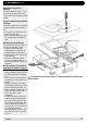

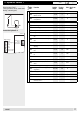


Table Of Contents
- Operation
- Dimensions and assembly
- Dimensions DC 12
- Dimensions of the basic housing DC 12
- Assembly DC 12
- 1. Loosen the screw of the front cover.
- 2. Take off the front cover.
- 3. With a screwdriver lift the base from the controller-print, see illustration right.
- 1. Hold the controller base to the assembly place and mark with an indication pin the mounting holes.
- 2. Drill the mounting holes and provide them with pegs.
- 3. Place the controller base, fit the screws (do not tighten), align the base, then drive the mounting screws fully home.
- Start up
- Troubleshooting
- Technical data
- Index

23
A
Adjuster code 1 ............................................................................................................................................10
Adjuster code 2 ............................................................................................................................................18
Adjuster with access code (expert level) ........................................................................................................9
Adjuster without code .....................................................................................................................................8
Assembly ......................................................................................................................................................15
C
Change operating mode .................................................................................................................................5
D
Dimensions ..................................................................................................................................................14
E
Electrical connection allocation ....................................................................................................................16
Error codes ...................................................................................................................................................19
Explanation of terms and abbreviations .......................................................................................................21
H
Hydraulic variant ..........................................................................................................................................17
I
Information about the plausibility check .......................................................................................................20
O
Operation .......................................................................................................................................................5
Q
Query of temperatures and operating data ....................................................................................................6
S
Start up .........................................................................................................................................................16
T
Technical data ..............................................................................................................................................21
Temperature sensor resistance.....................................................................................................................20
Troubleshooting ...........................................................................................................................................19
6Index
A0805