
Operating instructions
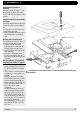

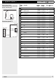


Table Of Contents
- Operation
- Dimensions and assembly
- Dimensions DC 12
- Dimensions of the basic housing DC 12
- Assembly DC 12
- 1. Loosen the screw of the front cover.
- 2. Take off the front cover.
- 3. With a screwdriver lift the base from the controller-print, see illustration right.
- 1. Hold the controller base to the assembly place and mark with an indication pin the mounting holes.
- 2. Drill the mounting holes and provide them with pegs.
- 3. Place the controller base, fit the screws (do not tighten), align the base, then drive the mounting screws fully home.
- Start up
- Troubleshooting
- Technical data
- Index
21
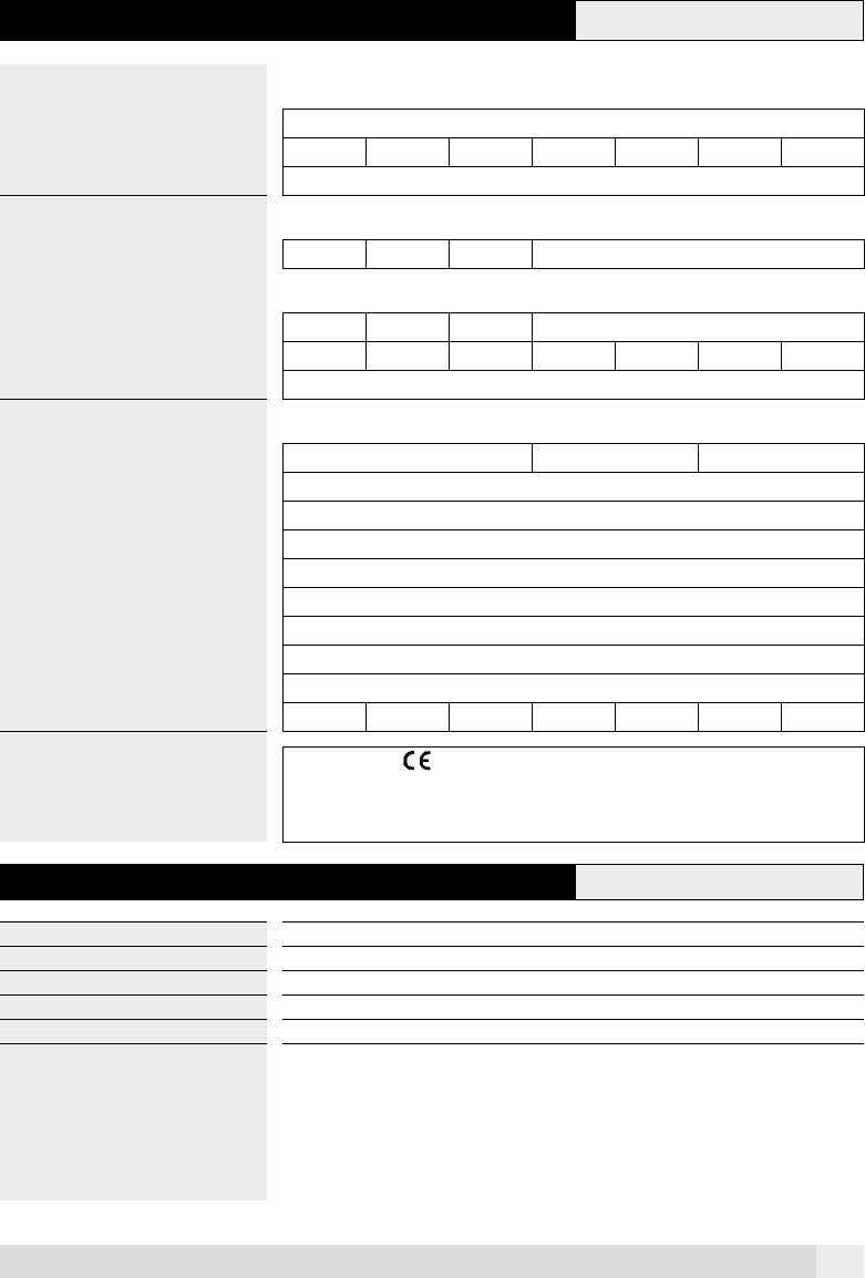
5 Technical data
DESIGNATION / TYPE DC 12
Voltage supply 230 V AC ± 10% 50 – 60 HZ
Max. power input 2.3 VA
Fuse 3.15 A
OUTLETS
Fully electronic relays 1
SWITCHING CAPACITY
Fully electronic relays 1 (1) A
Inputs sensor 2
Voltage, measuring circuit 12 V, V, protective insulation 4 kV
HOUSING
Montage Wall mounting
Dimensions H / W / D 153.5x135.3x48.7
Display LCD 96 Segment display
Operation 4 push buttons
Protection IP 40 – EN 60529
Protective class II – EN 60730
EMV EN 50082-1
EMV-Emission EN 50081-1
Ambient temperature 0 … 50°C
Hydraulic variants 1
Tests The controller is - conform according to the following EU guidelines:
• 70/23/EWG "Low Voltage-Guideline"
• 89/336/EWG "EMC guideline", including the amendment guidelines up to
90/68/EWG
5.1 Explanation of terms and abbreviations
h Hours
Actual value Measured value/temperature by sensor, displayed on controller.
K Kelvin, temperature difference
min Minutes
Set point value Temperature witch is to reach by the controller
A0805