
Operating instructions


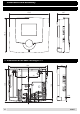
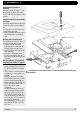

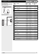


Table Of Contents
- Operation
- Dimensions and assembly
- Dimensions DC 12
- Dimensions of the basic housing DC 12
- Assembly DC 12
- 1. Loosen the screw of the front cover.
- 2. Take off the front cover.
- 3. With a screwdriver lift the base from the controller-print, see illustration right.
- 1. Hold the controller base to the assembly place and mark with an indication pin the mounting holes.
- 2. Drill the mounting holes and provide them with pegs.
- 3. Place the controller base, fit the screws (do not tighten), align the base, then drive the mounting screws fully home.
- Start up
- Troubleshooting
- Technical data
- Index
20
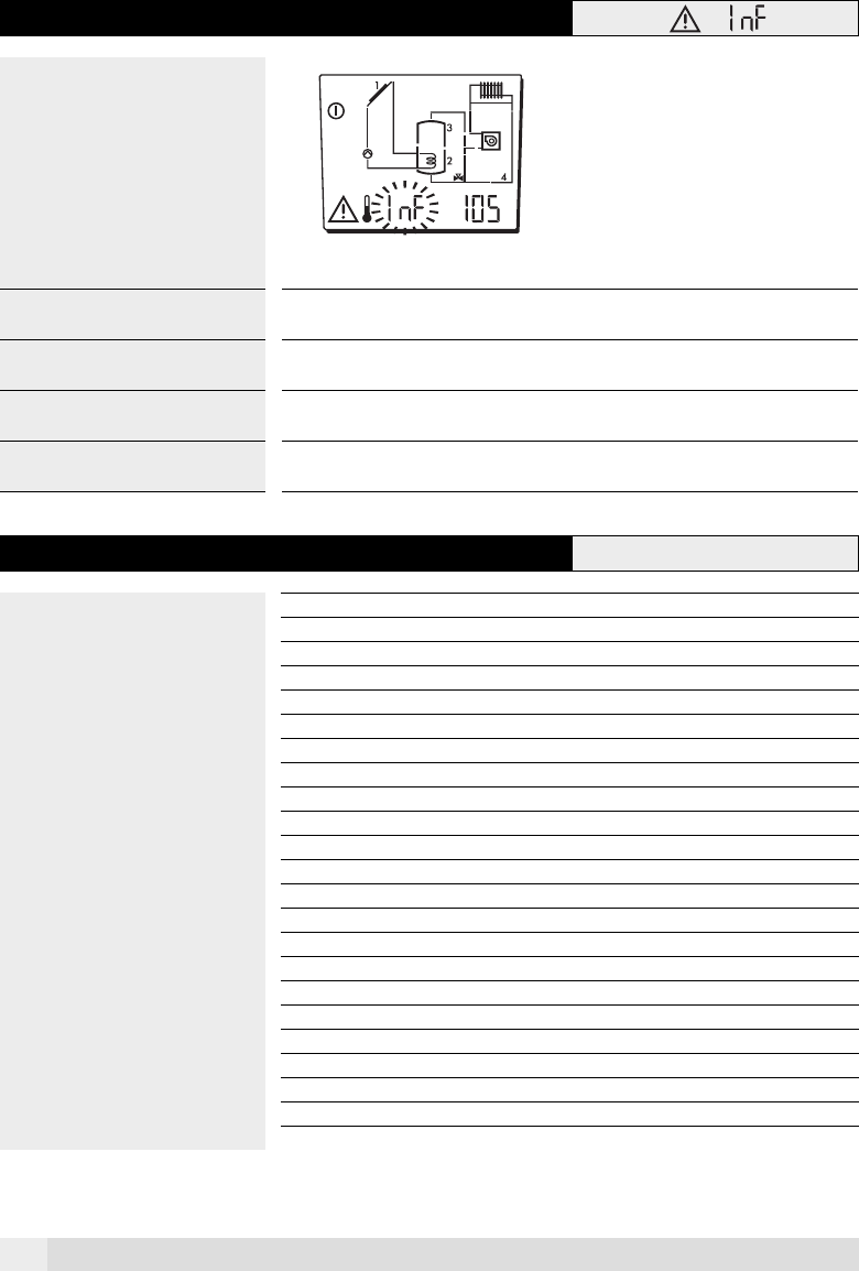
4.2 Information about the plausibility check
Info-display
The controller checks the system status
and signals errors. This is a plausibility
check of the data and serves to provide
information when malfunctioning occurs.
Info code Hydraulic Description Possible cause
101 all Collector max. temp. > as the collector protection
temp.
Wrong basic settings
(A 8-11) > (A 8-10)
102 all Increase collector tank for charging OFF > increa-
se collector tank for charging ON– 2K
Wrong basic settings
(A 8-02) > (A 8-01 - 2K)
105 all Set temp. tank 1 normal > max. temp. tank 1 Wrong basic settings SP 1
(A 8-62) > (A 8-59)
107 all Maximum temp. tank 1 > protection temp. tank 1 Wrong basic settings
(A 8-59) > (A 8-60)
4.3 Temperature sensor resistance
Temperature °C Resistance NTC 5 kΩ
-20 48'535
-15 36’475
-10 27’665
-5 21’165
0 16’325
5 12’695
10 9’950
15 7’855
20 6’245
25 5’000
30 4’029
40 2’663
50 1’802
60 1’244
70 876
80 628
90 458
100 339
105 294
110 255
115 223
A0805