
Operating instructions


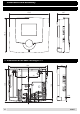
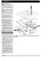

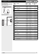

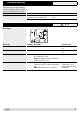

Table Of Contents
- Operation
- Dimensions and assembly
- Dimensions DC 12
- Dimensions of the basic housing DC 12
- Assembly DC 12
- 1. Loosen the screw of the front cover.
- 2. Take off the front cover.
- 3. With a screwdriver lift the base from the controller-print, see illustration right.
- 1. Hold the controller base to the assembly place and mark with an indication pin the mounting holes.
- 2. Drill the mounting holes and provide them with pegs.
- 3. Place the controller base, fit the screws (do not tighten), align the base, then drive the mounting screws fully home.
- Start up
- Troubleshooting
- Technical data
- Index
19
4 Troubleshooting
If after switching on, no display appears,
or an error message appears, the clarifi
-
cations in following table can be useful.
Statement Possible cause Solution
Display doesn’t appear Controller not under tension
External switch is on position "Off"
Examine the fuse, set external switch to
"ON"!
Wiring defect Open the controller and examine the wiring!
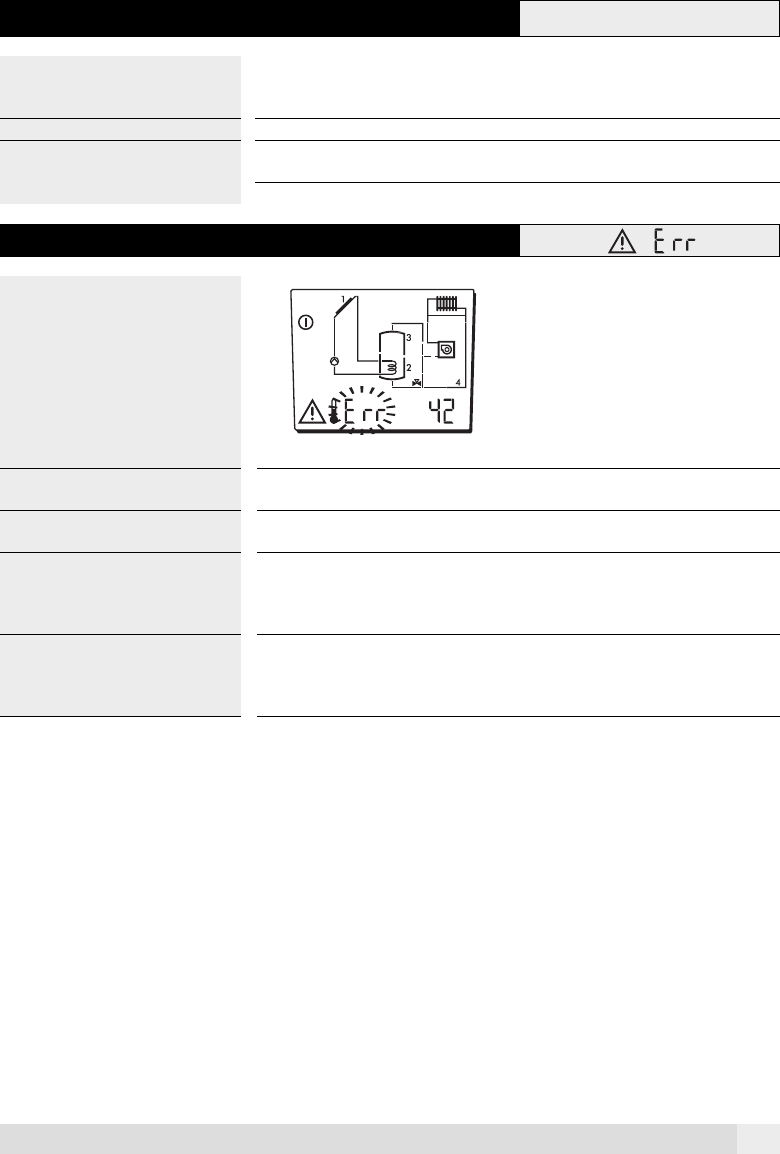
4.1 Error codes
Error-display
Error Code Hydraulic Description Possible cause
41 all Sensor 1 outside the measuring range. Short circuit of sensor / cut
out
42 all Sensor 2 outside the measuring range. Short circuit of sensor / cut
out
53 all Speed (revs.) of the pump does not correspond to
the controller given figure.
Note: With Adjuster 8-90 = 200, control OFF.
(Only in controller DC 12 P)
Pump blocked!
61 all Error when charging from collector 1 to tank 1
lower zone (temp. diff. collector–tank remains
high)
Note: With Adjuster 8-92 = 0, control OFF
No heat transfer, air in
charging circuit, no hy
-
draulic adjustment, outlet,
pump defect
A0805