
Operating instructions


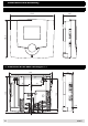
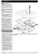

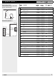


Table Of Contents
- Operation
- Dimensions and assembly
- Dimensions DC 12
- Dimensions of the basic housing DC 12
- Assembly DC 12
- 1. Loosen the screw of the front cover.
- 2. Take off the front cover.
- 3. With a screwdriver lift the base from the controller-print, see illustration right.
- 1. Hold the controller base to the assembly place and mark with an indication pin the mounting holes.
- 2. Drill the mounting holes and provide them with pegs.
- 3. Place the controller base, fit the screws (do not tighten), align the base, then drive the mounting screws fully home.
- Start up
- Troubleshooting
- Technical data
- Index
18
3.3 Adjuster code 2
The adjusters with code 2 are
valid for all hydraulic variants!
You receive the code 2 from
your heating expert.
Adju-
ster
Function Setting
range
Factory
setting
Unit Basic set.
Dat.:
8-05 Overheating protection on/off on -
If the temperature at the collector rises above the set collector maximum tempe-
rature (Adjuster 8-11) with the overheating protection active, solar charging will
be enabled independent of the set tank maximum temperature (Adjuster 8-59).
The set value for the speed control is determined by the temperature on the tank
sensor + setting value 8-64.
If the collector protection temperature Adjuster 8-10 or the tank protective
temperature (E8-60) is exceeded, solar charging is disabled.
8-09
Special heat capacity collector
fluid
on/off 4.1
kJ/
kg K
Special heat capacity of the collector fluid according to manufacturer’s
specifications.
8-10 Collector protective temperature 80÷130 130 °C
If the temperature at the collector sensor rises above the set value, solar char-
ging is disabled.
8-11 Collector maximum temperature 80÷130 95 °C
If the temperature at the collector sensor rises above the set values with the
overheating protection active (Adjuster 8-05), solar charging is enabled.
8-13 Frost protection function -50÷10 -50 °C
Deactivated if the setting is -50°C.
Solar pump is switched on if the temperature at the collector sensor < setting -
hysteresis.
Hysteresis 3 K is a given set value.
8-90
Error threshold for pump feed-
back signal
0÷200 100 %
The pump can be controlled. The controller measures the phase displacement
and compares it to the expected values.
Only for controller ES 5910 P / 5911 P. Error check is only carried out at
pump start-up.
0% = Only small deviations allowed
0 ÷ 199% = The larger the set value, the higher the allowed deviation
200% = Inactive, no pump error messages
8-91
Max. temperature difference
collector - tank
10÷80 50 K
If the difference in temperature between the collector and the tank temperature
rises above the set value when solar charging is active during the set time
(Adjuster 8-92), an error message (Err 61, 62, 63) is generated.
8-92
Waiting period error message
∆T collector - tank
0÷180 30 min
If the difference in temperature between the collector and the tank temperature
is too high when solar charging is active and during the set time, the error mes
-
sage is generated according to 8-91.
0 = Error message disabled
SET
A0805