
Operating instructions


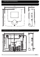
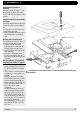

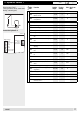

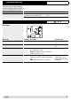

Table Of Contents
- Operation
- Dimensions and assembly
- Dimensions DC 12
- Dimensions of the basic housing DC 12
- Assembly DC 12
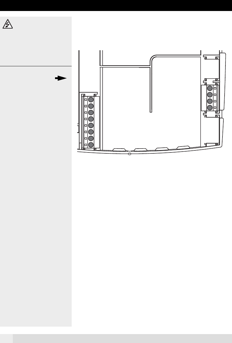
- 1. Loosen the screw of the front cover.
- 2. Take off the front cover.
- 3. With a screwdriver lift the base from the controller-print, see illustration right.
- 1. Hold the controller base to the assembly place and mark with an indication pin the mounting holes.
- 2. Drill the mounting holes and provide them with pegs.
- 3. Place the controller base, fit the screws (do not tighten), align the base, then drive the mounting screws fully home.
- Start up
- Troubleshooting
- Technical data
- Index
16
3Start up
The connections main volta-
ge on the left side No. 1-3/LN are
loaded with 230 V. These clamps may
be affected only dead, otherwise mor
-
tal danger exists because of current
impact.
3.1 Electrical connec-
tion allocation
Check up before start up if:
• the plant-main-switch (if existing) is
switched on!
• the controller is switched on!
• the correctly hydraulic variant is sel-
ected (Adjuster 4-06)
• the temperature set points values are
o.k.!
• the temperatures of the connected
sensors are shown on the display,
and there values are plausibly!
• a charge enterprise is possible do to
the collector temperature/storage
tank temperature!
Checking the controller
In order to test the controller and the ap-
propriate mechanism, the following clari-
fications can be accomplished after
switching on the DC 12:
1. All the segments are displayed briefly
(page 3)
1. The software number appears
(p. e. SW 1.4)
If the controller display then reverts to
normal, the internal function test was
successful.
L N N 1 2 N N 3
B1 B2
TT
Pump
solar charging
Not
used
Not
used
Voltage supply
230 V / 50 Hz
Collektor 1
sensor 1
Storage tank 1
sensor 2 bottom
Connections
sensors
Connections
net
Example: Hydraulic variant 1
A0805