
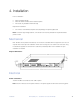
User guide

DC Power
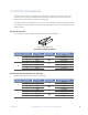
Use the supplied DC power connector for the DC Power supply. Connect a local 24~48VDC power supply to
the power connector. Make sure that the wire terminals are securely tightened. The ground contact is a
chassis ground, and must be connected to prevent damage or injury during high voltage events.
The DC power supplies use a PPTC resettable fuse, no customer replacement is required.
Note: The power terminals are polarity sensitive. Attach the positive DC wire to the V+ terminal only.
AC Power
Connect a local 115~240VAC power supply to the power connector using the supplied AC power cord.
The outlet must be grounded for safe operation. Turn OFF the power switch on the power supply before
connecting or disconnecting the power.
Note that there is a 1A fuse in the AC socket which may be replaced when blown. Contact RLH for
replacement fuses.
On the left corner of rear panel, a screw is used for connecting the chassis to the protective ground. Be
sure to make this connection using a thick wire.
Warning: The system must be securely connected to a good protective ground for safety. All
interconnected equipment must be grounded for maintaining signal integrity as well. Ground potential
faults may also damage the interface ports.
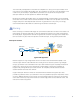
E1/T1connections
The E1/T1 ports on RLH-TG Mux are used for connecting to T1/E1 equipment such as the telephone
exchange or PCM terminals.
Up to 16 E1/T1 ports are supported. T1/E1 port impedance are 120Ω for twisted pair cables or 75Ω for
coax. The T1/E1-120Ω RJ45 sockets are default for ports.
The T1/E1-120Ω connection cable is made with RJ45 connectors and a breakout cable that is supplied
with the unit. Refer to the RJ-45 T1/E1 pinout information in Section 3. Components.
When making up a cable assembly in the field, note that pin-1 and pin-2 should use the same twisted
pair, so should pin-4 and pin-5. T1/E1 service can set the actual service quantity by NMS, set the exact
T1/E1 channels received by local equipment from remote equipment, realizing T1/E1 service one point
to multi-point unidirectional transmission function.
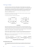
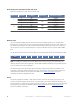
By NMS, T1/E1ports provide local loop back and remote loop back, each set of 8 T1/E1 ports loopback
can be set independently, and by the DIP switch RA on front panel T1/E1 indicators can be controlled to
indicate local or remote ports LOS and AIS status. The local and remote loop back definition is shown in
the following diagram.
18! RLH Industries, Inc. - 16 Channel T1/E1 over GE with Fiber! Installation