
User guide
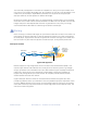
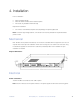

T1/E1Port Connections
There are 4 ports on each T1/E1 module, with each port carrying two T1/E1 channels. The T1/E1
connections are made using a breakout cable that splits the combined port on the modules into
separate T1/E1 ports for easy connection to existing lines.
T1 adapter cables are included with each unit. The T1 port impedance is 120Ω for twisted pair cables
and uses RJ45 connectors. Refer to the following pin assignment charts for wiring information on the
breakout cables.
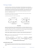
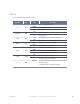
RJ-45 male pins chart
For connection to T1/E1 modules on both sides of the RLH-TG multiplexer.
!!!!!!!!!!!!!!!!!!!!!!!!!!
"#$%&#$'!($)*+,-!.,--)%'+$/',%!012'+1!.,34!5/*
!!!!!!!!!!!!!
6$781!93:3:;<! ! ! 0'=!">'/+#1?!01@'%'/',%!
0'=!
%)-71A!
B,/1! !
5$718! ! "/$/1! ! C<D6<!+$A*!'%*'+$/,A?!*1@'%'/',%! !
C<D6<!=$+E1/!8,??!$8$A-!'%*'+$/',%!
F%G!C/#1A%1/!'%/1A@$+1!+$%!%,/!A1+1'21!
C<D6<!
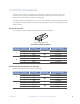
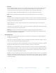
2.4.4 E1 Port
6#1A1!$A1!HI<J!C<!=,A/?!,%!/#1!A1$A!=$%18!7K!+,%@'&)A'%&!<I9!C<D6<!+$A*?3!6#1!
C<! =,A/?! '-=1%*1%+1! $A1! C<;<9Lȍ! @,A! />'?/1*! =$' A ! +$781?! ,A! MNȍ! @,A! +,$O3! 6#1!
C<;<9Lȍ!PQRN!?,+E1/?!$A1!*1@$)8/!@,A!=,A/?3! !
!
S'&!93R3:!PQRN!+,%%1+/,A!='%!?1T)1%+1! !
!
!
FB!
(8'%EG! C/#1A%1/! '%/1A@$+1! #$?! =$+E1/!
8,??!
F@@G! C/#1A%1/! '%/1A@$+1! #$?! C<D6<!
=$+E1/!8,??!
(8'%EG!%,A-$8! !
F%8K! >#1%!
/#1! 9
%*
!*'=!
?>'/+#!'?! ?1/!
FSS4! /#'?!
*'=! ?1//'%&?!
>'88! 71!
2$8'*3!
<
?/
!!
FSS!
C<D6<!?'&%$8!$8$A-!?/$/)?!'%*'+$/',%!
F%G! ! C<D6<!'%/1A@$+1!?'&%$8!8,??!
(8'%EG! ! C<D6<!'%/1A@$+1!UV"!$8$A-!
F@@G!%,A-$8! !
5C0WXF0C
P1-,/1! 1T)'=-1%/! 8'%E! ?/$/)?!
'%*'+$/',%!
!
FB!
F%G!$**A1??'%&!A1-,/1!XU.!
F@@G!%,/!$**A1??'%&!A1-,/1!XU.!
9
%*
!!
"1/!$++,A*!/,!/#1!<
?/
!*'=!?>'/+#! ! !
FSS!
V/! +,)8*! 71!
)?1*! >#1%!
Y5UB! 8'?/!
'?!
+,%@'&)A1*!
>A,%8K4! !
81$*'%&! /,!
-$%$&1-1%/!
+$%! %,/!
>,AE!
FB! ",@/>$A1!Y5UB!?1/!*'?$781*!
:
A*
!! BFWY5UB!
FSS! ",@/>$A1!Y5UB! ?1/!2$8'*! ! !
01@$)8/!VZ!$**A1??!<[93<[93<[93<[9!
!
FB!
R
/#
!!
6XZWVZ!
X$%)$88K!?1/!VZ!$**A1??!
!
FSS!
;!H!;! ! ! ! ! ! ! ! ! ! ! ! ! ! ! ! ! ! ! ! "#$%&#$'!($)*+,-!.,--)%'+$/',%!012'+1!\?1A!X$%)$8! ! Y<39
RJ-45 male connector pin diagram
T1/E1 Line
RJ-45 Pin
T1 Signal
Twisted Pair
Recommended Color
A
1
IN –
A
2
IN +
A
3
OUT –
A
4
OUT +
B
5
IN –
B
6
IN +
B
7
OUT –
B
8
OUT +
Pair
Blue
Pair
Blue White
Pair
Orange
Pair
Orange White
Pair
Green
Pair
Green White
Pair
Brown
Pair
Brown White
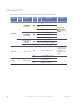
RJ-45 female pins description for CO side units
Breakout connections to T1/E1 lines for the CO side.
T1/E1 Line
RJ-45 Pin
T1 Signal
Twisted Pair
Recommended Color
A
1
IN +
A
2
IN –
A
4
OUT +
A
5
OUT –
B
1
IN +
B
2
IN –
B
4
OUT +
B
5
OUT –
Pair
Blue White
Pair
White
Pair
Orange White
Pair
Orange
Pair
Green White
Pair
Green
Pair
Brown White
Pair
Brown
Components! RLH Industries, Inc. - 16 Channel T1/E1 over GE with Fiber! 15