RLH Industries, Inc.
RLH Industries, Inc. Copyright © 2010 RLH Industries, Inc. All rights reserved. No part of this document may be copied or distributed without permission. The RLH logo may not be used for commercial purposes without the prior written consent of RLH and may constitute trademark infringement. Other company and product names mentioned herein are trademarks of their respective companies.
Contents 1. Important information General Safety Practices Special handling requirements Acronyms 2. 4 5 6 General Information Overview RLH 16 Channel T1/E1 over GE Features Applications Network Integration Fiber Optic Isolation Timing modes Timing Mode Reference Table 7 7 8 8 9 10 10 2. System Architecture Block Diagram Functional Description 11 11 3.
Contents 4. Installation Mechanical Physical dimensions Electrical Power connections E1/T1connections Ethernet/fiber optic connection 17 17 17 17 18 19 5. Troubleshooting E1/T1 Alarm LEDs on Lnk/Act LED off Ready LED does not blink Cannot set up T1/E1channel Downstream reporting slips 20 20 20 20 21 6.
Contents 7. Ordering Information 16 Channel T1 over Ethernet Multiplexer System SFP Optical Transceivers Replacement/Spare T1 modules Replacement/Spare Power Supplies 34 34 35 35 8. Specifications 9. Support Warranty Technical Support Contact Information Contents 37 37 37 RLH Industries, Inc.
1. Important information Intended Audience This guide is intended for use by knowledgeable telco/network installation, operation and repair personnel. Every effort has been made to ensure the accuracy of the information in this guide is accurate. However, due to constant product improvement, specifications and information contained in this document are subject to change without notice.
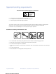
Special handling requirements Be careful when handling electronic components ATTENTION ELECTROSTATIC SENSITIVE DEVICES • This product contains static sensitive components. • Do not open the enclosure, there are no user serviceable parts. • Follow proper electrostatic discharge procedures. This product utilizes circuitry that can be damaged by static electricity. Before installing, discharge static electricity on your body by physically making contact with earth ground.
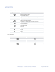
Acronyms Commonly used acronyms and abbreviations Acronym/Abbreviation B8ZS Description Bipolar 8 Zero Substitution AMI Alternate Mark Inversion CFJ Copper Fiber Junction (also referred to as Demarc) CO Central Office CPE Customer Premises Equipment Demarc Location of RLH CO equipment and Telco connection GPR Ground Potential Rise LED Light Emitting Diode Sub Subscriber NIU Network Interface Unit RX Receive TX Transmit Color abbreviations 6 Abbreviation Color BLU Blue GRN Gree
2. General Information Overview Thank you for selecting the RLH 16 Channel T1/E1 over IP/Ethernet multiplexer. This modular multiplexer unit can be used to provide T1/E1 communication channels over Ethernet or IP networks. The RLH 16 Channel T1/E1 multiplexer has many optional parameters, that can be modified by the user to suite different application requirements. Please read this guide carefully before installing the product.
• Resistant to packet loss, with PCM frame synchronization protection. • User definable encapsulation packet size for different applications. • Supports Ethernet encapsulation and UDP/IP protocol encapsulation. • Supports VLAN settings for T1/E1 service and in band VLAN management. • Jitter buffer resists packet delay variation (PDV).
The most widely used application of the RLH-TG multiplexers is to set up point to point wireless T1/E1 links using low cost wireless LAN bridges. RLH-TG multiplexers can work with most LAN bridges on the market. It may be necessary to adjust different parameters such as packet size and packet jitter absorption buffer size for best operation for different LAN bridges. Be aware that wireless LAN bridges have a very limited bandwidth.
!"#$%&$"' ()*+$' ,-"$&' (,&&$(".' ",' "#$' ,/"0,,%' /&1"2' 3,.1&4' 0)&4$%' ",' +14#"&1&4' ."%15$.'"#)"'()&'.$%1,/.+6'0)7)4$'"#$'$8/137$&"9':,'3%,"$("'"#$'$8/137$&"').' ;$++').'3$,3+$2'./%4$'3%,"$("1,&'0$<1($.';1"#'4,,0'$)%"#'(,&&$("1,&'1.'."%,&4+6' %$(,77$&0$09' =,,%' $)%"#' (,&&$("1,&' 7)6' )+.,' #1&0$%' "#$' ,3$%)"1,&' ,-' "#$' !"#$%&$"'3,%"2'()/.1&4'.$<$%$'3)(5$"'+,..$.9' ' Timing modes 1.
6$7.+(8! /.,.%&! 8*#1,18! $71! 9.8/1)! .%! :$;91! <3=><4! ?+7! $@@9.*$/.+%8! )1@.*/1)! .%! A.&3<3=>B3! ! A.&3<3C>B!:.,.%&!,+)1!8*#1,1!71?171%*1!).$&7$,! Equipment A Clock Mode Equipment A Clock Mode A Side B Side :$;91!<3C>IJ '0>IJ Loopback Loopback Equipment A & BK+/1! clocks Master Master *9+*G!,+)1! *9+*G!,+)1! synchronous Adaptive Adaptive :.,.%&!,+)1 :.,.
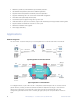
! ! ! ! ! ! ! ! ! ! ! ! ! ! ! ! ! ! ! ! ! ! ! ! ! ! "#$%&#$'!($)*+,-!.,--)%'+$/',%!012'+1!.,34!5/*! ! ! ! ! ! ! ! ! ! ! ! ! 2.2 Function Description 6#1! +,71! ,8! (09:;<:9=>! '?! /#1! 60@A>$+B1/! C7,+1??'%&! )%'/3! =/! /7)%+$/1?! <:! *$/$!?/71$-4!C)//'%&!/#1!*$/$!'%/,!!#1$*17?3!6#1! !In! !the ! ! ! reverse ! ! ! ! ! ! ! !direction, ! ! ! ! ! ! ! ! !packets ! ! ! "#$%&#$'!($)*+,-!.,--)%'+$/',%!012'+1!.
LED’s LED indicator definitions are shown below.
Dip Switches There are four DIP switches on the front panel. Refer to the DIP switch table below. Label Switch Number Definition T1 packet loss alarm indicator Setting ON 1 LED Description ON Ethernet interface cannot receive T1 OFF Ethernet interface has T1 packet loss Blinking Normal operation LED_MODE T1 signal alarm status indicator OFF ON T1 interface signal loss OFF T1 interface signal AIS alarm Notes Only when DIP switch 2 is set to OFF will this setting be valid.
F@@G!%,/!$**A1??'%&!A1-,/1!XU.! "1/!$++,A*!/,!/#1!'/+#! ! ! V/! +,)8*! 71! )?1*! >#1%! Y5UB! 8'?/! '?! +,%@'&)A1*! FB! ",@/>$A1!Y5UB!?1/!*'?$781*! >A,%8K4! ! :A*! ! BFWY5UB! 81$*'%&! /,! There are 4 ports on each T1/E1 module, with each port carrying two T1/E1 channels. The T1/E1 -$%$&1-1%/! connections are made using a breakout cable that splits the combined port on the modules into +$%! %,/! separate T1/E1 ports for easy connection to existing lines.
RJ-45 female pins description for Sub side units Breakout connections to T1/E1 lines for the Sub side. T1/E1 Line A B RJ-45 Pin T1 Signal 4 IN + 5 IN – 1 OUT + 2 OUT – 4 IN + 5 IN – 1 OUT + 2 OUT – Twisted Pair Recommended Color Blue White Pair White Orange White Pair Orange Green White Pair Green Brown White Pair Brown Ethernet ports There are five RJ45 Gigabit Ethernet electrical ports and one Gigabit optical port on the rear panel. Ethernet built-in layer-2 switch function.
4. Installation Prior to installation: • • • Check for shipping damage Check the contents to ensure correct model and options Have a clean, dry, installation environment ready Required for installation: • 18V~74VDC or 100~240VAC local power source, depending on the power supplies used Note: To maintain high voltage isolation, units at each end must be powered from separate isolated power sources. Mechanical RLH-TG Mux can be placed at the table top or mounted in a standard EIA 19” equipment rack.
DC Power Use the supplied DC power connector for the DC Power supply. Connect a local 24~48VDC power supply to the power connector. Make sure that the wire terminals are securely tightened. The ground contact is a chassis ground, and must be connected to prevent damage or injury during high voltage events. The DC power supplies use a PPTC resettable fuse, no customer replacement is required. Note: The power terminals are polarity sensitive. Attach the positive DC wire to the V+ terminal only.
/+!,(F/.@?+.%/!(%.).=1*/.+%$F!/=$%>,.>>.+%!C(%*/.+%3! ! 'R! QS"4! :8?+=/>! ?=+2.)1! F+*$F! F++?! E$*N! $%)! =1,+/1! F++?! E$*N4! 6! :8! ?+=/>! F++?! E$*N!*$%!E1!>1/!.%)1?1%)1%/FR4!$%)!ER!/#1!).?!JU!+%!C=+%/!?$%1F!:8!.%).*$/+=>!*$%! E1! *+%/=+FF1)! /+! .%).*$/1! F+*$F! +=! =1,+/1! ?+=/>! 5V"! $%)! UW"! >/$/(>3! ;#1! F+*$F! $%)! =1,+/1!F++?!E$*N!)1C.%./.+%!.>!>#+D%!$>!P.&!O3A3A@OX! RLH-TG Mux RLH-TG Mux ! P.&!O3A3A@O!:8!F++?!E$*N! ! JIÆ;I! :8! *+%%1*/.
5. Troubleshooting This section describes common mistakes and faults that may occur during installation and maintenance. E1/T1 Alarm LEDs on There are two groups of LEDs, PKT LOS and LOS for T1/E1 alarms LEDs. When T1/E1 LOS LED is on, loss of T1/E1 signal fault is detected by RLH-TG Mux. Possible causes include: • The downstream equipment such as telephone exchange or PCM terminal is powered off. • The T1/E1 cable connection looses or broken.
Different LAN domain When two RLH-TG Mux’s are in different Ethernet broadcast domains, IP headers must be used, and packets will be routed by a gateway router, try following: • Check if the default gateway IP is defined correctly. • Check if the local and remote IP is set correctly. • Check for any conflicts in IP or MAC addresses. • Make sure the transmission network has enough bandwidth. Downstream reporting slips Check if the downstream equipment has correct clock mode.
6. Web Manager Both Web Server and SNMP management are supported through any one of two user data ports of RLH-TG Mux. The management has three sections: Status, Configuration and System. User name and password are ! ! ! ! ! ! ! ! ! ! ! ! ! ! ! ! ! ! ! ! ! ! ! ! ! ! "#$%&#$'!($)*+,-!.,--)%'+$/',%!012'+1!.,34!5/*! ! ! ! ! ! ! ! ! ! ! ! ! required to enter the sections of Line Test Configuration and system. Both the default user name and password are “admin”.
! ! ! ! ! ! ! ! ! ! ! ! ! ! ! ! ! ! "#$%&!'$()*+,!-+,,(%.*$/.+%!012.*1!-+34!5/)3! ! ! ! ! ! ! ! ! ! ! ! ! ! ! ! ! ! ! "#$%&!'$()*+,!-+,,(%.*$/.+%!012.*1!-+34!5/)3! 6.&37389:! ! ;8!5.%1!"/$/(+?,$/.+%! !"# $%&'()*+,-(%&. T1/E1 Line Status Information !"#"/.01+2(31.3%&'()*+,-(%&.,&4.5,+,61-1+7.(&7-+*3-(%&. . ! 6.&37389:! ! ;8!5.%1!"/$/(+?,$/.+% Configuration @#.
Ethernet management parameters ! ! ! ! ! ! ! ! ! ! ! ! ! ! ! ! ! ! ! ! ! ! ! ! ! ! "#$%&#$'!($)*+,-!.,--)%'+$/',%!012'+1!.,34!5/*! ! ! ! ! ! ! ! ! ! ! ! ! Parameters 6$7$-1/178! ! Ethernet Port Status "/$/)8! Options 9:/',%8! ! Port "172'+1!>,3! Service Number 5'%H! ":11*! Link Speed Duplex Description ;<:=$%$/',%! ! 6 Ethernet Ports Numbers ;/#17%1/! 8172'+1! >,3?! 8)::,7/! $/! -,8/! @A! +$:'/$=B8-$==! Ethernet service No.
E1/T1 line management interface E1/T1 service management parameters setting are given below. E1/T1 service management parameters Parameters Options E1 T1/E1 T1 Encapsulation Level 1~5 Yes Use IP Encapsulation No Port E1 data size encapsulated in E1/T1, N=1~5 optional, corresponding to 256×N byte(E1).The bigger the packet is the more data each packet encapsulated, the lower overhead it has. Bandwidth efficiency will be raised and delay will be increased.
! ! ! ! ! ! ! ! ! ! ! ! ! ! ! ! ! ! ! ! ! ! ! ! ! ! "#$%&#$'!($)*+,-!.,--)%'+$/',%!012'+1!.,34!5/*! ! ! ! ! ! ! ! ! ! ! ! ! ! ! ! ! ! ! ! ! ! ! ! ! ! ! ! ! ! ! ! ! ! ! ! ! ! ! "#$%&#$'!($)*+,-!.,--)%'+$/',%!012'+1!.,34!5/*! ! ! ! ! ! ! ! ! ! ! ! ! ! ! ! ! ! ! ! ! ! ! ! ! ! ! ! ! ! ! ! ! ! ! ! ! ! ! "#$%&#$'!($)*+,-!.,--)%'+$/',%!012'+1!.
! ! ! ! ! ! ! ! ! ! ! ! ! ! ! ! ! ! "#$%&!'$()*+,!-+,,(%.*$/.+%!012.*1!-+34!5/)3! ! ! ! ! ! ! ! ! ! ! ! ! ! ! ! ! ! ! "#$%&!'$()*+,!-+,,(%.*$/.+%!012.*1!-+34!5/)3! ! 6.&!7389:! ! ;5<=!,$%$&1,1%/!.%/1>?$*1@AB9!;5<=!/$CD1! VLAN management interface(4)- VLAN table ! 6.&!7389:! ! ;5<=!,$%$&1,1%/!.%/1>?$*1@AB9!;5<=!/$CD1! ! 6.&!7389E!;5<=!,$%$&1,1%/!.%/1>?$*1!@7B9;5<=!*+%?.&(>$/.+%!*+%?.>,!@!*D.*F!=GHI!/+!1%/1>B!! ! !6.&!7389E!;5<=!,$%$&1,1%/!.%/1>?$*1!@7B9;5<=!*+%?.&(>$/.+%!*+%?.>,!@!*D.
VLAN Management parameters Parameters Options Description 802.1Q VLAN Mode (E1/T1) Ethernet Port VLAN Configuration VLAN Management E1/T1Port VLAN Configuration VLAN Table Next 802.1Q add VLAN tag on Ethernet frame. Q in Q add operators VLAN (S-Tag) in 802.1Q. Realizing VLAN stack. Suitable for the network with VLAN Priority, ensuring E1/T1 Q in Q QoS. Ethernet port number 1~7 Ethernet No. 1~6 is Data/Uplink port, 7 is internal trunk.
/+!81/!D5EF!/$&!P+7!/#1!,$%$&1)!D5EF!,1,K178L!/.*J!+PP!(%/$&N3!Q%/$&!.%/17%$H!/7(%J!$H8+R!.P! .%/17%$H!/7(%J!/$&!.8!%11)1)4!./!#$21!/+!*+,6HG!$!7(H1!$8!S!71,+/1!P.78/T4!/#$/!.8!/+!8$G4!*+%P.&(71! 71,+/1!1U(.6,1%/!D5EF!/$KH1!P.78/HG4!/#1%!*+%P.&(71!D5EF!/$KH1!P+7!/#1!1U(.6,1%/!*+%%1*/1)! C./#! ,$%$&1,1%/! B-3! 9P! ,$%$&1,1%/! P$.H(71! *$(81)! KG! *+%P.&(7.%&! D5EF4! 81/! )+C%! ).6V! /+! ).8$KH1!D5EF3! Network 5.
! 6'&!7389:!*1;$)$-1/1>?!>1+,21>@!A! After recovering default parameters, it will display access failed, as shown on the following screen. B;/1>!>1+,21>'%&!*1;$)$-1/1>?4!'/!C'<13! E#1%! *1;$)$-1/1>?!$<>1$*@!>1+,21>1*4!C1!%11*!/,!>1?/$>/!F1D!"1>21>3! ! 6'&!73898!*1;$)$-1/1>?!>1+,21>@!G! Default parameters recovery 2 .
! B.&!C3D?E!(:&8$)1!+%<.%1!FG(:<+$)!%19!:8+&8$,! ! B.&!C3D?E!(:&8$)1!+%<.%1!FG(:<+$)!%19!:8+&8$,! "/1:!H7!=1<1*/!:8+&8$,!/I:14!*<.*J!K:&8$)1!/+!=/$8/3! Step 2: select program type, click Upgrade to start. "/1:!H7!=1<1*/!:8+&8$,!/I:14!*<.*J!K:&8$)1!/+!=/$8/3! 619! :8+&8$,! 9.<
! 6'&!7389:!);&<$*1!,%='%1!>8?@A1=1+/!$%!$;;='+$/',%!A,B/C$<1!B'=1! DB/1
! 6.&!7389:;!(<&=$)1!+%>.%1!?7@A+<1=$/1!B(**1BBC(>>D! System reboot !"#"$ %&'(()*+,+)&-* * ! 6.&73E9F!G1H++/!1I(.<,1%/! Reboot equipment Specification 6. ."/ 012134),* J/!B(<<+=/B!K!+=!:F!L:!<+=/B4!7!ML!1>1*/=.*$>!<+=/B!$%)!:!ML!+!<+=/3!:! ! ."5 6/*47)&8913&* -+,<>D!N./#!JOP9O!M3Q;8!=1*+,,1%)$/.+%! L.&#/!L:!R+=/B!"(<<+=/1)3L:!<+=/!.,<1)$%*1!L:9:S;ȍ!C+=!/N.B/1)!<$.=!*$H>1B!+=! Q7ȍ!C+=!*+$T!?O#1!GUE7!L:9:S;ȍ!$=1!)1C$(>/!C+=!<+=/B@! L%)9/+91%)!)1>$D!?,.%.,(,!)1>$D!B1//.%&@! ! d!:;,B! ! "#$%&#$.
7. Ordering Information 16 Channel T1 over Ethernet Multiplexer System RLH - TG - X X -1 Manufacturer Model Designation Product Designation Powering Option A = Dual 115VAC Power Supplies V = Dual 24~48VDC Power Supplies C = 115VAC and 24~48VDC Power Supplies Number of T1 Modules 1 = Single T1 Module (8 T1 Channels) 2 = Dual T1 Modules (16 T1 Channels) 3 = Single E1 Module (8 E1 Channels) 4 = Dual E1 Modules (16 E1 Channels) Optical SFP transceivers are ordered separately, one SFP required per chassis.
Replacement/Spare T1 modules RLH - XX 8 -1 Manufacturer Model Designation Module Style T1 = T1 Module (8 Channels) E1 = E1 Module (8 Channels) Channels Designation Each T1/E1 Module has 8 Channels Two T1/E1 modules may be installed into each chassis Please contact your RLH sales representative for pricing and delivery information Replacement/Spare Power Supplies RLH - 16PS - XX -1 Manufacturer Model Designation Product Designation Power Supply Configuration AC = 115~240VAC Power Supply DC = 24~48V
8. Specifications Model RLH-TG-XX-1 16 T1 5 GE electrical ports 1 GE SFP optical port Interfaces IP Ports 5 GE electrical ports and 1 GE SFP optical port Complies with IEEE 8802.3, 802.1Q, 802.1P Speed and duplexing auto-negotiating or manual selectable T1 Ports 16 T1 ports supported in 2 plug-in modules/B8ZS Complies with G.
9. Support Warranty RLH is recognized throughout the U.S. and offers the only UNCONDITIONAL LIFETIME WARRANTY in the telecommunications industry. We are very proud of our warranty which simply states that our Fiber Optic Link Assemblies are warranted to be free of defects in material and workmanship for the LIFE OF THE PRODUCT.
RLH Industries, Inc. 936 N. Main Street, Orange, CA 92867 USA T: (714) 532-1672 F: (714) 532-1885 38 Please contact your RLH sales representative for pricing and delivery information. Specifications subject to change without notice. RLH Industries, Inc.