
User guide
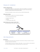


Connect ethernet cables
• Attach ethernet cables to the RJ-45 ethernet ports labeled LAN1 through LAN4 on the front panel of the iMux.
Connect data/phone equipment
Attach the breakout adapters and cables depending on your iMux module configuration.
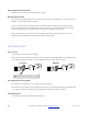
Connect T1 cables
• Attach the breakout adapter cable to the DB-25 connector on the T1 module.
• Connect the RJ-45 T1 connectors to the breakout adapter cables.
Connect Analog Phone (POTS) FXO/FXS cables
• Attach the phone cables directly to the RJ-11 connectors on the analog phone module.
Attach RS-232 Data Cables
• Attach the breakout adapter cable to the connector on the RS-232 module.
• Connect the RS-232 data connectors to the DB-9 connectors on the breakout adapter cable.
Attach 2/4W Data/SCADA Cables
• Attach the data cables directly to the RJ-11 connectors on the analog phone module.
Refer to the iMux User Guide for pin out and port configuration information.
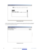
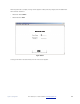
Start the system
Turn each iMux ON using the power switch on the rear panel. The system will initialize and start up. The LED
indicators on the front panel will flash during initializing and stop flashing after setup is done. The iMux is now
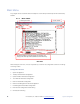
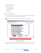
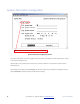
operational and may be configured as desired.
Refer to the iMux User Guide for additional configuration information.
24! RLH Industries, Inc. • 866-DO-FIBER • www.fiberopticlink.com! Quick Start