
User guide
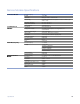

No.
Symptom
Probable Cause
Corrective Action
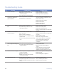
8
Optical LOS alarm is on.
• If the self loop of the optical ports is
normal, and the connection of the optical
cables is correct, the fiber cables are faulty
or the distance is too long.
• The TX and RX optical cable connections
are reversed.
• Test and/or change the optical cables
• Change to a long distance optical module.
• Exchange the TX and RX fiber cables.
9
The equipment of one side of
the optical connection is
normal, and the other has a
LOS alarm.
• The fiber optic cable is faulty.
• The optical module has malfunctioned.
• Test and/or change the optical cables.
• Self loop the equipment that has the LOS
alarm to test the optical module.
• Contact your support representative.
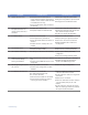
10
E1 interface alarms.
• Coaxial connector is faulty.
• The E1 equipment is powered off.
• The E1 TX and RX interface connection is
reversed.
• The alarm of the E1 tributary slot is not
masked.
• Replace the coaxial connector.
• Verify functioning E1 signals to the iMux.
• Check the E1 TX and RX connections.
• PRess the MASK button mask the E1
tributary alarm.
11
V.35 interface alarms.
• Clock settings do not match.
• The V.35 connector is bad.
• Check the V.35 interface configuration.
• Check the V.35 connector and wiring.
12
OE module isn’t switching.
• OE startup lock function is set incorrectly.
• Check optical interface parameters
configuration.
• Check OE switching protection status.
13
PRBS test showing bit errors,
or test is OK but always
showing red indicators.
• Non-compliant use of framing in unframed
type.
• The user lookup PRBS test result is in the
wrong place.
• Configure the correct type in unframed.
• Generally, the user should check the
results in the PRBS testing screen.
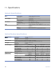
14
Cannot login using front panel
LCD controls.
• Input key sequence is incorrect.
• The LCD Login Configuration has been
redefined.
• Check LCD Login Configurations.
15
E1 interfaces have bit errors.
• Impedance is not matched.
• E1 cables exceed length limits.
• E1 connector are faulty.
• 120Ω connection cables are not twisted.
• The E1 terminal unit does not share a
common ground with the iMux.
• Verify the impedance of the E1 equipment
is the same as the iMux module.
• Confirm that the E1 cable is no longer than
200 meters.
• replace the E1 connectors.
• Check the 120Ω RJ45 connector that pins
1 & 2 are twisted, and pins 3 & 4 are
twisted.
• Confirm that the E1 terminal unit and the
iMux are properly grounded in accordance
with proper electrical standards.
Troubleshooting! 117