
User guide

External alarm port
Pin No.
Signal
Port 1
Port 1
Port 2
Port 2
1
Positive Input
8
Negative Input
4
Positive Input
9
Negative Input
110
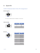
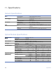
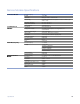
3. Alarm port:
4. External alarm port:
The voltage offset between positive and negative input: 3 ~ 60VDC
Input current range: 0.5 ~ 8 mA
Pin No. Signal
1
2 RMIN LEDA
3 RMIN BUA
4 RMAJ LEDA
5 RMAJ BUA
6 RMIN LEDB
7 RMIN BUB
8 RMAJ LEDB
9 RMAJ BUB
Pin No. Signal
1 Positive input
Port
8 Negative input
4 Positive input
Port
9 Negative input
4 1
9 8
5
5
The voltage offset between positive and negative input: 3 ~ 60VDC. Input current range: 0.5 ~ 8 mA
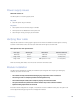
10."Troubleshooting
First Step: Isolate the problem
Following the the installation procedure will greatly speed any troubleshooting. It is designed to isolate
different parts of the system during installation.
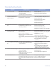
Isolating the source of trouble is essential to determining the steps needed to fix the problem. Most installation
problems can be easily fixed in the field once the problem is properly identified.
Common Issues
Most problems encountered during installation and testing can be attributed to these 4 issues:
• Problems with the incoming signal
• Problems providing correct power to the system
• Problems with the copper connections wiring due to nicking, scoring or poor terminating
• Problems with the fiber optic cable
• Problems with missing or improperly installed modules
• Problems with configuration
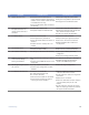
RLH iMux systems are built to the highest standards and fully tested before leaving the factory.
Isolating and ruling out common issues with the installation will help determine if there is a problem with the unit
itself.
114! Troubleshooting