RLH Industries, Inc.
RLH Industries, Inc. Copyright © 2013 RLH Industries, Inc. All rights reserved. No part of this document may be copied or distributed without permission. The RLH logo may not be used for commercial purposes without the prior written consent of RLH and may constitute trademark infringement. Other company and product names mentioned herein are trademarks of their respective companies.
Contents 1. Important Information Intended Audience 8 Conventions 8 General Safety Practices 8 2. Introduction Product Description 9 Standard Features 9 Application Diagrams 10 Front Panel 11 Front Panel LEDs 11 Module Status LEDs 12 LAN/MGMT Port LEDs 12 Optical Module LEDs 12 Rear Panel 13 4 Channel E1 Module 13 4 Channel T1 Module 13 4 Channel RS-232 Module 14 4 Channel V.
Site Requirements 21 Site selection 21 Typical application environments 22 Required power sources 22 Test Equipment 22 For T1 service 22 For analog phone service (POTS) 22 For RS-232 service 22 4. Quick Start Easy Installation 23 Before starting 23 Install the iMux 23 Connect power 23 Connect fiber cables 23 Connect ethernet cables 24 Connect data/phone equipment 24 Start the system 24 5.
Scheduling Job Management 40 Networking Service Management 41 Network TroubleShooting Operation 42 LCD Login Configuration 44 Event Management 45 Event Class Processing Configuration 46 Event Alarm Processing Configuration 47 System Profile Management 48 Configuration File Management 50 Terminal File Transfer Operation 54 Tributary Slot Interface Selection 55 E1 Interface Configuration 56 V.
External Clock Configuration and Monitoring 86 External Clock Configuration 86 External Clock Monitoring 87 OE Protection Switching Automatic laser shutdown 88 89 Equipment Status Monitoring 90 Status Monitoring Screen 90 Local site tributary card setting 91 Remote site tributary card setting: 92 Performance Monitoring 93 Aggregate/Dsx1 Performance Monitoring 93 Performance Monitoring Settings 94 Trunk Ethernet Performance Monitoring 95 Path Alarm/State Monitoring 96 Interface Alar
10. Troubleshooting First Step: Isolate the problem 114 Common Issues 114 Power supply issues 115 AC power 115 Verifying fiber cable 115 Module installation 115 Troubleshooting Guide 116 11. Specifications General Specifications 118 Optical Module Specifications 118 Service Module Specifications 119 12. Ordering Information Base Systems 120 Port Modules 120 Optical Modules 121 13.
1. Important Information Intended Audience This manual is intended for use by knowledgeable telco/network installation, operation and repair personnel. Every effort has been made to ensure the accuracy of the information in this manual is accurate. However, due to constant product improvement, specifications and information contained in this document are subject to change without notice. Please refer to the iMux User Guide for additional information.
2. Introduction Product Description The iMux is a powerful fiber optic modular multiplexer capable of providing up to 16 channels of T1, RS232, 2/4 wire data and analog phone FXO/FXS services, plus four built-in 10/100M Ethernet ports, over a single fiber. These services are supplied by the modules, up to four, that each offer four lines of communication and may be installed in any combination. Spares or add-on modules may be ordered separately and are field installable.
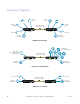
Application Diagrams POTS (FXO) T1 2/4 Wire Data POTS (FXS) T1 2/4 Wire Data Fiber Optic Cable Up to 74 mi.
Front Panel MAJ WK LSR ON TX RX LOS WK LSR ON TX RX LOS E1/V35 1 2 3 4 PWR MIN LCK LB K ACO EXT CLK SL-2100 1 2 3 RDI 4 LOS/LOF/AIS LAN1 LAN2 LAN3 LAN4 MGMT CRAFT RST Front Panel LEDs LED Color Name MAJ RED Major Alarm ON condition Major alarm event is present and OFF condition Normal operation being signaled through rear panel alarm connector. MIN YEL Minor Alarm Minor alarm event is present and Normal operation being signaled through rear panel alarm connector.
Module Status LEDs E1/V35 1 2 3 4 IMux slot number N1 LAN2 LAN3 LAN4 MGMT PWR LCK ACO PORTS MAJ MIN LBK RDI ACO 1 2 3 4 Port number on each module CRAFT LOS/LOF/AIS RST LED Name Color PORT Installed port slot RED No module is installed at this port number GRN A module is installed at this port number Module port status for RED No connection is detected to that port any installed module GRN Active connection is attached to that module port E1/V35 Condition Note: Although the por
Rear Panel Any of the modules may be plugged into any position, called a Tributary Slot. These are referred to as TB1~TB4. 3-2 Rear Panel Refer to the Specifications section for additional information.
4 Channel RS-232 Module 4xRS-232 module, HD68 to 4 DB-9 connectors to RS-232 interface. Breakout adapter cable is included. (f) RS232 tributary card 1 5 DB-9 Female DCE RS232 6 9 Pin Description I/O 1 2 3 4 5 6 7 8 9 DCD TXD RXD DTR SG DSR RTS CTS RI Output Output Input Output GND Input Output Input Output Any kind of the above cards is allowed to plugged into tributary slot 1~4. (c) 4V35 tributary card (TB1~TB4) 4 Channel V.35 Module 4*V35 card, HD68 to 4*M34 Connectors to V.35 interface.
4 Channel Analog Phone (POTS) Modules Analog phone uses RJ-11 connectors and are supplied as FXS/Sub side and FXO/CO side modules. The FXO/CO module is connected to a central office or PBX, and the FXS/Sub module is connected to the customer telephone. Each line number FXO raises the same line number FXS, and provides 64k voice bandwidth. Use an FXS module on each end for ringdown operation where connection to phones on both ends of the system is desired.
4 Channel 2/4 Wire Analog Data/Audio/SCADA Module Four Analog 2/4 Wire Data/Audio/SCADA modules use RJ-11 connectors. Each channel has 300Hz ~ 3.4kHz bandwidth. Analog Channel FXO FXS Input PIN 1 PIN 4 4 PIN RJ-11 Female Output Pin Description 1 Tip 4 Ring 2 Tip 3 Ring 4 Channel 2/4 Wire Analog Data/Audio/SCADA/E&M Module Four Analog 2/4 Wire Data/Audio/SCADA/E&M modules use RJ-45 connectors. Each channel has 300Hz ~ 3.4kHz bandwidth. E&M type is set in software.
Setting E&M Jumpers and Switches Use the J2 jumper and the J4 DIP switches to set the E&M module mode to Master or Slave depending on the placement of the iMux in the network. The diagram on the following pages will help you determine the correct settings for your application. Refer to the diagram below for configuration settings.
Analog E&M 4-Wire Audio Operation PBX Tie-Line Cisco Equipment Slave Master 4 Wire E&M Card 4 Wire E&M Card E&M E&M Fiber Optic Cable (-48V) iMux PBX (-48V) iMux Tie-Line Cisco Equipment On-hook On-hook -48V E detect 7 E Off-hook -48V E 7 M 6 detect Off-hook E Off-hook Off-hook M -48V ptc GND 6 M detect -48V 8 On-hook On-hook T R 4-Wire Audio T1 R1 Trunk Circuit 8 ptc 2 T 3 R 5 T1 4 R1 4-Wire Audio 4-Wire Audio T 2 R 3 T1 5 R1 4 Signalling
Acronyms Commonly used acronyms and abbreviations Acronym/Abbreviation B8ZS Bipolar 8 Zero Substitution FXO/CO Central Office Side Equipment FXS/Sub Subscriber side equipment LED Introduction Description Light Emitting Diode RX Receive TX Transmit RED Red LED color YEL Yellow LED color GRN Green LED color RLH Industries, Inc. • 866-DO-FIBER • www.fiberopticlink.
3. Before Installing Observe Special Handling Requirements Be careful when handling electronic components ATTENTION ELECTROSTATIC SENSITIVE DEVICES • This product contains static sensitive components. • Handle the T1/E1 cards and optical modules by their faceplates only. • Follow proper electrostatic discharge procedures. This card utilizes circuitry that can be damaged by static electricity.
Prepare for Installation Check for shipping damage Carefully unpack and inspect the unit and accessories. Contact RLH immediately if any components are damaged or missing. Electronic components, fiber optic cable, and accessories have special handling requirements to prevent damage and enhance system reliability. If the iMux will be relocated in the future, save the cartons and protective packaging material.
Typical application environments Install the fiber optic cable prior to installing the iMux system. Required power sources You will need an acceptable power source. The iMux system accepts 90 ~ 240VAC (47Hz ~ 63Hz) and 12, 24 or 48VDC (9 ~ 75VDC) depending on the model. The F.C.C. requires telecommunication equipment to withstand electrical surge that may result from lighting strikes. This equipment has been tested and found to comply with the F.C.C. requirement.
4. Quick Start Easy Installation Before starting • Review the safety information in section 1. Important Information • Familiarize yourself with the iMux and it’s modules as described in section 2. Introduction • Know how to handle fiber optic cable, have a suitable installation environment with the correct power, and have the necessary test equipment as described in section 3.
Connect ethernet cables • Attach ethernet cables to the RJ-45 ethernet ports labeled LAN1 through LAN4 on the front panel of the iMux. Connect data/phone equipment Attach the breakout adapters and cables depending on your iMux module configuration. Connect T1 cables • Attach the breakout adapter cable to the DB-25 connector on the T1 module. • Connect the RJ-45 T1 connectors to the breakout adapter cables.
5. Configuring the System Management Interface Using the VT-100 port Any PC with an operating system that supports the VT-100 Craft Port can be used as a console. The following instructions utilize the VT-100 Craft Port on a PC running Windows 98/2000/NT. 1. Use the supplied RS-232 cable and connect the console port to the COM port of the console PC. 2. Use a telnet program such as Windows Hyper Terminal to perform the console management operations.
Startup Loading Screen Once a mode has been selected, the system continues the startup procedure utilizing the built in self-diagnostic function during the boot procedure. The self-diagnostic function includes system memory access test, system main clock test and tributary card access test. Self-diagnostic Screen 26 RLH Industries, Inc. • 866-DO-FIBER • www.fiberopticlink.
After the system test is complete, the login screen appears. Unless previously changed, enter the default User Name and User Password. • Default User Name: admin • Default Password: 1234 Login Screen Once login information has been entered, the main menu screen appears. System Configuration RLH Industries, Inc. • 866-DO-FIBER • www.fiberopticlink.
Main Menu Any changes that are made and saved will modify the current Startup Profile except for the Profile Factory Defaults. 4-1-2 Main Menu Current Location Current location Show System Show systemName name Press the Function keys the canfunction accesskeys. the item faster. Access items faster by using Pressing [F3] brings up the online help and has definitions of the function keys.
Testing/Monitoring Screens j. Equipment Status Monitoring k. Performance Monitoring l. Path Alarm/State Monitoring m. Loopback/V.54 Testing n. PRBS Testing o. Event Browsing System Configuration Either the local or remote iMux units may be selected for configuring. Select the Local[F2] or Remote[F3] units by using the function keys prior to making any other menu selections. Each subsequent menu will display which unit (local or remote) you are changing settings on.
System Information Configuration Note: This shows the local or remote device you are configuring. System Information Configuration Screen The system administrator can enter the system name the location of the system, and the contact person. Entries must be 256 characters or less. Set the system clock by entering the correct time. This screen shows the running time of the system and the software version. After making any changes, press Confirm[F2] to save them.
Device Networking Configuration Device Networking Configuration Screen Setting the device IP You can set the device IP of the front panel MGMT port in this screen. The MGMT port IP address is static, so make sure there isn’t a conflict on your network prior to confirming the settings. Press Confirm[F2] to execute your changes and direct the system to use those settings immediately. Your changes will now be reflected as the running IP status.
User Account Management User Account Management Screen Setting System Access Groups The iMux provides three kinds of the user groups. • Admin The administrator group account can execute all functions. • Control The controller group account can execute all functions except the System Configuration. • Monitor The monitor group account only can monitor the system. User accounts may be added [F2], deleted [F3], or edited [F4]. 32 RLH Industries, Inc. • 866-DO-FIBER • www.fiberopticlink.
Selecting Add[F2] opens the Add User Account screen. This is where new user accounts are set up. Each user may have their own password and be assigned to a Group. Setting the Auto-Logout to 0 (zero) seconds disables Auto-Logout. User accounts may also be disabled in this menu without deleting them. SNMP Agent Configuration System Configuration RLH Industries, Inc. • 866-DO-FIBER • www.fiberopticlink.
Setting the Trap IP The iMux can assign four sets of the Server IP address for sending the Traps. Enter the IP address and port number information on each line as required. Three community names may also be set. Default names are preconfigured, but may be changed using the menu items [F5], [F6] and [F7].
[F5] File Name: Enter the file name of new firmware. ForUser Local File source selection: Thename. screen [F6] Login Name: Enter the remote server’s user will show the available file Login Password: Enter the remote server’s password. stored in the system. Local File Local File For Local File source selection, the screen will show the available file stored in the system.
Software Upgrade and Reboot Operation After the software upgrade configuration is completed, the Software Upgrade and Reboot Operation can be executed from this menu. Upgrade Status When you execute the Upgrade[F2] commend item in the local or remote side, it will display the upgrade status including: Start upgrading! Connecting! Transferring! Loading! DeCompressing! Flash writing! Sending! Upgrading complete! None 36 RLH Industries, Inc. • 866-DO-FIBER • www.fiberopticlink.
Upgrade Error Messages If the software upgrade has an error, it will display one of the following error messages: Internal error! Local file not found! Information incomplete! Upgrading is running! Connect failed! Transfer failed! Read failed! Image file too large! Disconnect failed! Decompress code failed! Invalid image format! Abort by user! None! When user selects the [F3] Reboot commend item in local or remote side, it will show the message: Software Reboot Status When user selects the [F3] Reboot co
When the iMux Booting screen appears, select a profile for loading. Use the up and down arrow keys to change selections, and press the enter key to load the selected profile. Note: If no key is pressed within three seconds, then the system will automatically download the previous profile. Press any key to hold and pause the screen. Reboot profile Selection Screen 38 RLH Industries, Inc. • 866-DO-FIBER • www.fiberopticlink.
Network Time Synchronization Network Time Synchronization Screen You may set the System clock manually, or use the network time synchronization function. To use a time server press [F1] and enter the time server IP address and time zone, then execute the Synchronize[F5] command. The system clock will be automatically set via Internet.
Scheduling Job Management Scheduling Job Management Screen The Scheduling Job Management function directs the iMux to perform certain job functions at specific times. The system administrator can arrange the schedule for each job. Add Scheduling Job Screen 40 RLH Industries, Inc. • 866-DO-FIBER • www.fiberopticlink.
• Job Type: Periodic / One shot / Booting • Time Type: Every Interval / Every Day Every Interval: The system will do the selected job at every time interval. Every Day: The system will do the selected job at the desired time every day, according to the system time. Interval (min.
When using the FTP Server, the device can act as a client or server. However the memory storage is small, so the user can only to perform a software upgrade and save EventLog operation. Note: If the software upgrade image is stored locally, and you restart or re-boot power, the software image will be deleted. Network TroubleShooting Operation Network Ping Operation Screen The iMux can ping an IP address to show whether it can link to a network location, and provide some information about that connection.
If the target IP ping succeeds, it will display the results similar to this: Successful Ping Results Screen If the target IP does not answer, it will timeout with no response. Ping Failure Screen System Configuration RLH Industries, Inc. • 866-DO-FIBER • www.fiberopticlink.
LCD Login Configuration LCD Login Configuration Screen E1/V35 1 2 3 4 PWR LCK ACO PORTS MAJ MIN LBK RDI 1 2 3 4 LOS/LOF/AIS ACO LAN4 MGMT CRAFT RST Front Panel LCD Controls The front panel login uses the UP, RIGHT and DOWN buttons pressed in a 4 key sequence in order to gain access using the front panel. Define this key sequence by setting the pass keys using the LCD Login Screen. Up uses the button on the front panel. Right uses the Down uses the button on the front panel.
Event Management Event Management Screen The iMux provides Event Management function that includes [1] Event Class Processing Configuration [2] Event Alarm Processing Configuration System Configuration RLH Industries, Inc. • 866-DO-FIBER • www.fiberopticlink.
Event Class Processing Configuration Event Class Processing Screen The event class processing configuration function can set the events of the configure, alarm, and operation to save in the flash or to send the trap. N is not save in the flash or not to send the trap Y is save in the flash or to send the trap Use the Confirm[F2] command to save the settings. Note: Confirm the send trap status if the NMS system does not receive an alarm trap. 46 RLH Industries, Inc. • 866-DO-FIBER • www.fiberopticlink.
Event Alarm Processing Configuration Event Alarm Processing Screen The event alarm processing configuration function controls how different alarm events are handled based on severity. These events may be set to save in flash memory or to send the trap. The four classes of the alarm severity are: [F1] Critical [F3] Major [F4] Minor [F5] Warning Note: Confirm the send trap status if the NMS system does not receive an alarm trap. System Configuration RLH Industries, Inc. • 866-DO-FIBER • www.fiberopticlink.
System Profile Management Profile Management Select [1] Profile Save Parameter Configuration and then Next[F2]. Profile Saving Configuration 48 RLH Industries, Inc. • 866-DO-FIBER • www.fiberopticlink.
Set the [F1] Auto Saving to ON and the auto saving interval in minutes to enable auto profile saving. From the Profile Management screen select [2] Profile Operation and then Next[F2]. Profile Operation This screen allows you to modify boot profiles. Although there are are four booting profiles, only Profile I and Profile II may be user modified. Profile Factory Default and Profile Factory Default (IP Address: 192.168.0.1) profiles may not be altered.
Configuration File Management Configuration File Management Screen You may upload or download profile configurations and easily apply it to any iMux. This allows allows you to load a profile, or upload a profile to a server for archiving, saving, or further distribution. A profile may be created at a remote location, uploaded to a server, and downloaded to another iMux for use. First, you will specify the server and file names using [1] Config Upload Configuration and [2] Config Download Configuration.
[1] Config Upload Configuration Config Upload Screen Enter the protocol, server, user and file information to upload.
[2] Config Download Configuration Config Download Configuration Screen Enter the protocol, server, user and file information to upload.
[3] Config Upload/Download Operation Config Upload/Download Screen Choose the Operation Target and Device Networking Config, then execute Upload[F2] or Download[F3] to begin the transfer. System Configuration RLH Industries, Inc. • 866-DO-FIBER • www.fiberopticlink.
Terminal File Transfer Operation Terminal File Transfer Screen Available files will be displayed in the file window. Choose the desired file and execute Receive[F2] or Send[F3]. Files may also be deleted by using Delete[F4]. 54 RLH Industries, Inc. • 866-DO-FIBER • www.fiberopticlink.
Tributary Slot Interface Selection Tributary Slot Configuration Screen The iMux can use different modules that mount into slots in the back of the unit. These slots are called Tributary Slots, and must be configured before they can be used. Note: The iMux has been pre-configured with appropriate settings for the Tributary Slots that were used at the time it left the factory. These settings were initially saved in both Profile I and Profile II.
E1 Interface Configuration [F3]Site: Select Local, Remote or All (both sites) by using the Space Bar, press the Enter key to select it. [F4]SlotId: Select 1~4 slots or All by using the Space Bar, press the Enter key to select it. [F3]ChId: Select 1~4 individual channel ID to setup or All by using the Space Bar, press the Enter key to select it. E1 Interface Configuration Screen Select the iMux site you want to change, the Tributary Slot ID, and the individual channel ID before configuring parameters.
Choose the Edit[F2] to set channel service types. E1 Channel Parameter Editing The [F1] Circuit Identifier lets you assign a name to the circuit if desired. The [F3] Service Mode setting has two service modes which can select OOS (Out of Service) or IS (In Service). Set the frame type with [F4] Frame Type. There are three types of E1 services available: FAS+CRC, FAS Only, Unframed. Set the line coding with [F5] Line Coding. There are two types of E1 line coding: HDB3 or AMI.
V.35 Interface Configuration Choose the site, slot and channel as described in the E1 Configuration section. V.35 Interface Configuration Note: If the EOC connection is closed, a symbol “-“ will be shown for each configuration. Choose the Edit[F2] to edit channel service types. V.35 Parameters Channel Editing 58 RLH Industries, Inc. • 866-DO-FIBER • www.fiberopticlink.
You can set the polarity of Tx or Rx clock to fit the requirement of different The [F1] Identifier lets you assign a name to the circuit if desired. kindCircuit of DTEs. The [F3] Service Mode setting has two service modes which can select OOS (Out of Service) or IS (In PCM31: 64K~1984K Service). Date Rate PCM30: 64K~1920K The [F3] Clock Source setting permits the use of an External clock source, or the Internal clock.
FXO/FXS Interface Configuration Choose the site, slot and channel as described in the E1 Configuration section. FXO/FXS Interface Parameters Configuration Choose the Edit[F2] to edit channel service types. FXO/FXS Parameters Channel Editing 60 RLH Industries, Inc. • 866-DO-FIBER • www.fiberopticlink.
T1 Interface Configuration Choose the site, slot and channel as described in the E1 Configuration section. T1 Interface Parameters Configuration Choose the Edit[F2] to edit the T1 channel service types. T1 Interface Parameters Configuration System Configuration RLH Industries, Inc. • 866-DO-FIBER • www.fiberopticlink.
Tributary TSA configuration Tributary TSA Configuration Screen The iMux provides five kinds of the Tributary TSA (Time Slot Assignments) : • Normal (All E1 channels) • 7E1+1V.35 (Seven E1 channels and one V.35 channel) • 3E1+1V.35 (Three E1 channels and one V.35 channel) • CH4<->CH5 (Four E1 channels and one V.35 channel) • CH8<->CH9 (Eight E1 channels and one V.35 channel) Note: The V.35 interface setting will be set to OOS (Out of Service) when mode1~mode4 is set to the V.35 interface.
1. Normal mode (All E1 channels) Normal mode (All E1 channels) Remote Local (1) In the normal mode, every channel can also do the PRBS testing with the corresponding channel in the remote side. In the normal mode, every channel can also do the PRBS testing with the corresponding channel in the remote side. E1 INT CLK V35 DTE Note: (1) The clock setting needs to conform. Refer to the following block diagrams. EXT V35 E1 INT 1.
2. Seven E1 channels and one V.35 channel mode Seven E1 channels and one V.35 channel mode TB2 TB1 TB2 TB1 Normal Normal Mode mode 7E1+1V.35 7E1+1V.35 Mode mode TB3 TB2 TB1 TB3 TB2 TB1 In this mode, user can also do the PRBS test which is like the figure as above. The remote side’ channel will generate the test pattern to corresponding channels in the local side.
3. channels Three E1 and one V.35 Four E1 andchannels one V.35 channel mode channels mode TB1 TB1 Normal Normal Mode mode 3E1+1V.35 7E1+1V.35 Mode mode TB2 TB2 TB1 TB1 In this mode, the user can also do the PRBS test as reflected in the figure as above. The remote side’s channel generates the test pattern to corresponding channels in the local side.
4. Four E1 channels and one V.35 channel mode Eight E1 channels and one V.35 channel mode TB2 TB1 TB2 TB1 Normal Normal Mode mode CH4"!CH5 CH4 Mode<-> CH5 (4E1+1V.35) Mode (4E1+1V.35) TB2 TB1 TB2 TB1 In this mode, user can also do the PRBS test as reflected in the figure as above. The remote side’s channel generates the test pattern to corresponding channels in the local side.
Optical Interface Parameters Configuration Optical Interface Parameters Configuration Screen Select the optical interface to configure and press Edit[F2] to enter the Edit Channel Screen. Optical Interface Parameters Editing Screen System Configuration RLH Industries, Inc. • 866-DO-FIBER • www.fiberopticlink.
[F1] Aggr Circuit Identifier OE 1 Circuit Identifier OE 2 Circuit Identifier Enter Circuit Identifier names as desired. [F3] Working OE (Working Optical Enable) Set the primary working optical interface. [F4] ALS (Auto Laser Shutdown) Please refer to the definition of ITU-T G.664, when the iMux detects LOS and the ALS function is enabled at the same time, then OE will shutdown the signal of Tx. It will detect the signal automatically every 100 seconds.
4-1-6 Trunk Ethernet Configuration Selection Trunk Ethernet Configuration Selection Trunk Ethernet Configuration Screen In the screen user can easy to switch the port function and allow to setting fast Ethernet rate configuration in Ethernet interface. Ethernet interface, QoS settings and VLAN configuration.
Trunk Ethernet General Parameter Config If the remote side shows no device or LOS, the screen will not show the remote side. Trunk Ethernet General Configuration Screen Set the [F1] VLAN function as desired. VLAN Function Mode Setting Ingress Filter Enable Description Drop frame associated with a VLAN for which that port is not in the member set. Disable Tag Aware Enable Disable Tag Only Enable Disable Disable ingress filtering. Tagged-based.
Trunk Ethernet Parameters Config Trunk Ethernet Parameters Configuration Set the local and remote ports as desired. Trunk Ethernet Parameters Configuration Slot Editing System Configuration RLH Industries, Inc. • 866-DO-FIBER • www.fiberopticlink.
Trunk Ethernet Port Rate Configuration Trunk Ethernet Port Rate Configuration You may change the Fast Ethernet port speed to another port speed. Each port may be set individually by setting the ingress and egress speed to desired speed. This setting may be extended to cover multiple network ports or limited to just either ingress or egress if needed. 72 • 1526 = 100M • 152 = 10M • Ingress = RX • Egress = TX RLH Industries, Inc. • 866-DO-FIBER • www.fiberopticlink.
Trunk Ethernet Port VLAN Config Trunk Ethernet VLAN Config Screen Begin setting up the VLAN configuration by using this menu. Note: The PVID (Port VLAN ID) must be between 1 and 4094. The PVID number set in this menu must also be used for the same port in the Trunk Ethernet VLAN Configuration screen. Egress Mode Mode Unmodified Untagged Tagged Description Do not insert or remove VLAN tag to/from packets sent out from this port.
Trunk Ethernet VLAN Table Config Management Trunk Ethernet VLAN Table Config Screen Select Add[F2] to add a VLAN configuration to the table. Trunk Ethernet VLAN Configuration Add Specify the VLAN Id and its associated port member using the same VLAN Id entered in the Trunk Ethernet Port VLAN Config screen. Select Confirm[F2] to add the configuration to the table. 74 RLH Industries, Inc. • 866-DO-FIBER • www.fiberopticlink.
Trunk Ethernet QoS Port Config Trunk Ethernet QoS Port Config Screen This screen specifies the QoS configuration for every trunk ethernet port. QoS Mode Mode Disable PortBased Description Turn off the QoS function for this port Turn on the the QoS function, and the priority of each packet received from this port is assigned by the following [Priority] setting. There are four priority levels, Queue1, Queue2, Queue3, and Queue4.
Trunk Ethernet QoS Schedule Config Trunk Ethernet VLAN QoS Schedule Config Screen This screen specifies the the packet egress scheduling configuration when QoS support is enabled. The packet scheduling is weighted round robin (WRR), the setting [Weight] is applied to the four queues. This approach prevents the lower priority frames from being starved out with only a slightly increased delay to the higher priority packets, and guarantee the minimal packet rate of one queue.
Trunk Ethernet QoS Tag Priority Config Trunk Ethernet QoS Tag Priority Config Screen Specifies the mapping of 3-bit tag priority to the four level priority, Queue1 ~ Queue4. Trunk Ethernet Tag Mark/Remark Config Trunk Ethernet QoS Tag Mark/Remark Config Screen Specifies the remarking mapping for tagged and retagged packets. System Configuration RLH Industries, Inc. • 866-DO-FIBER • www.fiberopticlink.
When the VLAN tags are entered as non-tagged packets, the 3-bit priority of the inserted tag will follow this configuration. When the Egress Mode setting is Retagged and the TagRemark setting is turned ON, the priority field of of the VLAN tag is replaced with this tag priority of the assigned queue. Data Port Parameters Configuration Data Port Configuration Screen In this screen you may configure different data rates for transmitting and receiving data. 78 RLH Industries, Inc. • 866-DO-FIBER • www.
Performance Management Threshold Configuration PM Threshold Configuration PM Threshold Configuration Screen The Performance Management setting allows you set a PM threshold value. If the PM value is equal or over the threshold’s value then it will issue the TCA alarm. If TCA alarm is enabled, the alarm of TCA will be released after it’s min/day setting. If the value is “ 0 ” the TCA will be disabled.
Dsx1 Interface Threshold Setting Dsx1 Threshold Parameters Setting You may use the function keys to modify the selected traffic link. There are two PM types: the Quarter (15 minutes), the Day (24 hours). Function Key [F6] Disable [F7] All Disable 80 Description Disable the PM TCA alarm on the selected E1 path by high light bar Disable the PM TCA alarm on the all selected E1 paths by the selection filters RLH Industries, Inc. • 866-DO-FIBER • www.fiberopticlink.
Dsx1 Threshold Parameters Editing Screen Function Key [F1] Line [F1] Line Setting Description LCV: Line Code Violation LES: Line Error Second LSES: Line Several Error Second LCV: Line Code Violation LES:Path Line [F3] Error Second PCV: Path Code Violation PES:Second LSES: Line Several Error Path Error Second Path Several Error Second PSES: [F3] Path PCV: Path Code Violation PES: Path Error Second PSES: Path Several Error Second System Configuration RLH Industries, Inc.
Aggregate Interface Threshold Setting Aggregate Threshold Parameters Setting Screen You may use the function keys to modify the selected traffic link. There are two PM types: the Quarter (15 minutes), the Day (24 hours). Aggregate Threshold Parameters Editing Screen 82 RLH Industries, Inc. • 866-DO-FIBER • www.fiberopticlink.
Fault Management Parameters Configuration 4-1-9 Fault Management Parameters Configuration Fault Parameter Configuration Fault Parameter Configuration Screen The iMux provides fault management functions by setting the alarm severity for each failure alarm. SL-2100 provides fault management function by setting the alarm severity for each failure alarm. System Configuration RLH Industries, Inc. • 866-DO-FIBER • www.fiberopticlink.
Alarm Severity Config Alarm Severity Config Screen The administrator can define alarm severity and easy to manage alarm status. If the alarm severity configured as Critical or Major, the red MAJ LED turn on when an alarm occurs. Otherwise, both Minor and Warning alarm will turn on the yellow MIN LED. 84 RLH Industries, Inc. • 866-DO-FIBER • www.fiberopticlink.
Power Failure Monitoring Parameter Config Power Failure Monitoring Parameter Config Screen Provides the capability of power monitoring. When ON is selected and the power module has failed, an alarm will be issued. System Configuration RLH Industries, Inc. • 866-DO-FIBER • www.fiberopticlink.
External Clock Configuration and Monitoring External Clock Config and Monitoring Screen To provide more stable synchronous for the system, you can use the built-in optional external clock module. This provides the extra external clock input for the whole system’s reference. 4-1-10.1 External Clock Configuration External Clock Configuration External Clock Configuration Screen 86 RLH Industries, Inc. • 866-DO-FIBER • www.fiberopticlink.
User can select OOS (Out of System) or IS (In System) to turn on or off the external clock input. When the EOC (External Optional Clock) connection has failed or the External Cock module is not installed, the configuration will not show. 4-1-10.2 External Clock Monitoring External Clock Monitoring External Clock Monitoring Screen If the External Clock Module is installed, the EquipStatus will show as Equipped, and Unequipped will be shown when the module is absent.
4-1-11 OE Protection Switching OE Protection Switching 1 2 3 User theOEactive module locked or released The user maycan makemake the active moduleOE locked or released and manually restart theand OE module from this screen. module menual restart from this screen. OE 1. Configuration 1.
Automatic laser shutdown and restart concept The ALS mechanism implemented in SL-2100 is refered to the ITU Recommendation ITU-T G.664. The ALS mechanism can be enabled or disabled in 4-5 Optical Interface Parameters Configuration. Automatic laser shutdown The ALS mechanism implemented in iMux is referred to the ITU Recommendation ITU-T G.664. The ALS mechanism can be enabled or disabled in the Optical Interface Parameters Configuration screen.
Equipment Status Monitoring Status Monitoring Screen On the equipment status monitoring screen, you can see an overall view of the alarm status of the interlinked rack systems, and it also provides the operator with direct access to the tributary card modes.
Local site tributary card setting: Local site tributary card setting Lomeaning – means Local Sitesite Lo is Local When a user card isplugin plugged card into TB1 When in(Tributary TB1, this Slot 1), this row will show TB card data here. row will showing TB card data here. In this example, when a module is installed, User can the info forthen pressing [F2] accoreding will let you set parameters that slot. press [F2] key setting it.
Remote site tributary card setting: Remote site tributary card setting: Re is meaning Remote site indicates Remote Site site ReReis–meaning Remote When user plugin card in TB1 and TB2, this row will showing TB card data accoreding the When card plugged into TB1 in (Tributary Whenahere. useris User plugincan card TB1 Slot and 1), thisthen show[F2]B.. TB card data In this it. info press keyhere. setting TB2, row thiswill row will showing TB card example, when a module is installed, pressing data here.
Performance Monitoring Performance Monitoring Selection Screen The performance monitoring screen shows the Aggregate/Dsx1 and Ethernet PM (Performance Monitoring). 4-1-13.1 Aggregate/Dsx1 Performance Monitoring Aggregate/Dsx1 Performance Monitoring Performance Monitoring Screen The performance monitoring screen will show the valid quarters and valid days had been counted for each card. Select the card and access to System Configuration RLH Industries, Inc. • 866-DO-FIBER • www.fiberopticlink.
The Performance Monitoring Screen will show the valid quarters and valid days had been counted for each card. Select the card and access to next screen to see the detail performance data. Function Key Description Clears all PM counters on the selected monitoring path [F6] Reset [F7] Reset All Clears all PM counters on the monitoring paths Performance Monitoring Settings Performance Monitoring Settings Function Key PM Type have five kindsMode [F3] PM Type CurrQuart Description Current Quarter 1.
Trunk Ethernet Performance Monitoring Trunk Ethernet Performance Monitoring Screen Menu Item Description Tx TX byte or packet counter. This counter is incremented once for every data byte/packet of a transmitted packet. Rx RX byte or packet counter. This counter is incremented once for every data byte of a received and forwarded good packet. RX byte/packet count includes both forwarded and dropped good packets. For mirror RX forwarded packets, if these are not good packets they will not be counted.
Path Alarm/State Monitoring Path Alarm Monitoring Screen This screen shows all of alarm status for all monitoring path. Some diagnostic testing work will cause an alarm to be triggered, and the status of loopback (V.54) and PRBS action shown as well. Interface Alarms 96 Interface Possible Alarms OE LOS Aggr LOF, RDI, AIS T1/E1 LOS, LOF, RDI/AIS V35 LOS Ethernet Link LAN/WAN Link Fxo/Fxs On-Hook, Off-Hook RLH Industries, Inc. • 866-DO-FIBER • www.fiberopticlink.
4-1-15 Loopback/V.54 Testing Loopback/V.54 Testing Loopback/V.54 Testing Screen the diagnostic speed V.35 data channel For diagnosticFor purposes, low speed E1purpose, or V.35 datalow channels and E1 highor speed aggregate signals canand be locally loop-backed remotelyaggregate loop-backed.signal high orspeed can be locally loop-backed or remotely loop-backed. Loopback Testing E1 Module There are four types of loopback functions for the E1 Module: 1. Tributary Local Loopback (for each E1 signal) 2.
c. Aggregate Remote Loopback (for all multiplexed E1 signals) d. Tributary Remote Loopback. (for each E1 signal) Users can select whether to diagnose a specific channel or all channels under thecanloopback / V.54 Testing. Users select whether to diagnose a specific channel or all channels under the loopback / V.54 Testing. a. b. c. Local Site d. Remote Site Local site Remote site a. TributaryLocalLoopback: In the Loopback/V.
Notice function key [F8] If the EOC (embedded channel) had broken such as in the aggregate Note: function key [F8] remote loopback state then had [F8] Undo-AgReLBK can beremote usedloopback to re-built the If the EOC (embedded channel) broken such as in the aggregate statechannel. then Undo-AgReLBK[F8] be used to re-built the EOC won't channel.enable. But, if the EOC But, if optical can signal lose, this function optical signal is lost, this function won't be enabled.
4-1-16 PRBS Test PRBS Test PatternAnalysis Analysis Pattern Pattern Generate Generate Pattern PRBS Testing Screen The pattern of PRBS is 215-1(unframing). Both E1 and V35 are able The pattern of PRBS is 215-1(unframing). Both E1 and V35 are able to perform this testing. to perform this testing. In order to do the self-test, any E1 data link can be selected to have a PRBS test. The tested result will be shown in the number of error bits as well as its error ratio.
One way PRBS test step: One way PRBS test step Remote Local Ana iMux SL-2100 GEN SL-2100 iMux 97 System Configuration RLH Industries, Inc. • 866-DO-FIBER • www.fiberopticlink.
The round trip PRBS test function operating step. The round trip PRBS test function operating step Loopback Loopback Path A path A Remote SL-2100 iMux Loopback Loopback Path B B path Loopback Loopback Path C path C Local Ana GEN iMux SL-2100 Refer to the loopback test function to verify the loopback setting. To do the PRBS test, first set the path (Loopback A, B or C)to which you want to test. The local device Please refer to loopback the loopback test function verify the loopback setting.
Event Browsing 4-1-17 Event Browsing Event Browsing Screen Clear Ram Log [F4]: clear all history events after the system booted. Menu Item Clear Ram Log[F4] Description Clears all history events since the system last booted. Clear Flash Log[F5]: If the event-saving function is be enabled. F5 will Clear Flash Log[F5] If the event-saving function is enabled, this will clear all history events stored in flashclear memory. all history events store in Flash memory. (ref: 4-3-12.
4-2 LCD Operating Instructions 4-2 LCD LCD Operating OperatingInstructions Instructions SL-2100 provides a easy way to set the configuration, maintenance, and SL-2100 provides providesaaeasy easyway waytotoset setthe theconfiguration, configuration, maintenance, SL-2100 maintenance, andand testing by LCD and button. testing by LCD LCD and andbutton. button. testing by 6.
Menu Tree LCD4-2-1 MenuLCD Tree Passward: _ ______ (See (Modify Password refer to 4-3-11) Password:_ LCD Login Configuration) ---System ----Network Service [Site] ----SNMP(ON/OFF) ----TELNET(ON/OFF) ----FTP(ON/OFF) ----WEB(ON/OFF) ----Profile Operation [Site/ProfID] ----Load ----Save ----Reboot Operation [Site] ----Reboot(DOWN) ---Tb Config ----E1 [Site/Slot/Ch] ----FrameType (FAS+CRC/FAS/OFF) ----LineCoding (HDB3/AMI) ----Service (IS/OOS) ----T1 [Site/Slot/Ch] ----FrameType (FAS+CRC/FAS/OFF) ----LineCoding
----FXX [Site/Slot/Ch] ----Service (IS/OOS) ----TSA [Site] ----TSA (Normal/2E1+2V.35/7E1+1V.
---Oe Protect Sw ----Current Status [Site] ----WorkingOe (Status:1/2) ----OELocked (Status:-/ON/OFF) ----SwitchNo (Status:1-99) ----LeftRelSec (Status:1-99999) ----OE1Tx (Status:ON/OFF) ----OE2Tx (Status:ON/OFF) ---Oe Lock/Release [Site] ----Lock OE (Status:(ON)/Release OE(DOWN)) ----Lock OE (Status:(OFF)/Lock OE(DOWN)) ---Oe Restart [Site/Oeld] ----Restart DOWN (Restart OK/ Restart fail) ---Oe Test [Site/Oeld] ----RestartTest DOWN (RestartTest OK/ RestartTest fail) ---FM Config ----Pwr Fail Mon Cfg [Site/P
---Loopback/V.54[Site] ----Aggr ----LLBK (ON/OFF) ----RLBK (ON/OFF) ----RRLBK (ON/OFF) ----UndoAgReLBK (ON/OFF) ----E1 [Slot/Ch] ----LLBK (ON/OFF) ----RLBK (ON/OFF) ----T1 [Slot/Ch] ----LLBK (ON/OFF) ----RLBK (ON/OFF) ----V.35 [Slot/Ch] ----ANA (ON/OFF) ----DIG (ON/OFF) ----REM (ON/OFF) ---PRBS Testing[Site] ----E1 [Slot/Ch] ----PTGEN (ON/OFF) ----PTANA (ON/OFF) ----PTANA Result (Status:Error/BER) ----T1 [Slot/Ch] ----PTGEN (ON/OFF) ----PTANA (ON/OFF) ----PTANA Result (Status:Error/BER) ----V.
7. Web Operating Interface Using the web interface To be able to use the web interface, the IP address must be enabled and configured via the command line interface. Enter the iMux IP number into a browser window to access the web interface. Refer to Device Networking Configuration for IP set up information. RLH Industries, Inc. iMux Web Interface Login Screen The default user Name is admin and the password is 1234. Refer to User Account Management for user name and password information.
After login, the equipment status screen is shown. You can display the Local site, Remote site, or Local+Remote.
Saving or loading profiles Use the pull-down menu to display the Local side, Remote side, or Local+Remote. If the profile had been changed earlier, during the configuration processing, the title in the blue header bar will show Config Modified. After making any changes, select Profile Management to save changes in Profile I or Profile II.
8. Telnet Operating Interface SNMP management Use the RJ-45 port to connect to the SNMP management system. To be able to use the telnet interface, the device IP must be configured first. RLH Industries, Inc. iMux SNMP Login Screen Refer to Device Networking Configuration for IP set up information. The default user Name is admin and the password is 1234. Refer to User Account Management for user name and password information.
1. External clock port: 8 RMAJ LEDB 9 RMAJ BUB 4 9. Appendix 8 Craft & External Alarm Ports Pin Assignment 4. External alarm port: External clock port Pin 4 and Pin 8 of 54 DB9 are used for E1 PCM data or TTL Clock inpot. 1 Pin No. Signal 1 Positive input 8 Negative input 4 Positive input 9 Negative input Port 99 8 8 6 Port Pin 4 and Pin 8 of DB9 are used for E1 PCM data or TTL Clock input. 2.
4. External alarm port: External alarm port 54 98 PinPin No.No. Signal Signal Port Port 1 1 1 8 8 Positive Positiveinput Input Port Port 2 4 4 9 9 1 5 Negative Negativeinput Input Positive Positiveinput Input Negative Negativeinput Input The voltage offset between positive and negative input: 3 ~ 60VDC. Input current range: 0.5 ~ 8 mA The voltage offset between positive and negative input: 3 ~ 60VDC Input current range: 0.5 ~ 8 mA 10.
Power supply issues PWR LED remains off The iMux system isn’t receiving proper power. AC power • Check AC power using a multimeter. DC power • Check power at the DC terminals using a multimeter. • No AC power can be detectable on the DC power line. • Check wiring for nicking, scoring or poor termination. Verifying fiber cable Verify the fiber cable when incoming signal is good, but the other end indicates that a fiber signal is not being received.
Troubleshooting Guide No. 1 Symptom VT-100 cannot login Probable Cause Corrective Action • CIT cable connection invalid. • Check cable link • Baud Rate incorrect and com port incorrectly selected. • Check baud rate and com port • Check login name and password • Input wrong account and password 2 The equipment screen alarm indicators are different from physical indicators. • Alarm configurations incorrectly set. • Physical alarm connector faulty.
No. 8 Symptom Optical LOS alarm is on. Probable Cause Corrective Action • If the self loop of the optical ports is • Test and/or change the optical cables normal, and the connection of the optical • Change to a long distance optical module. cables is correct, the fiber cables are faulty • Exchange the TX and RX fiber cables. or the distance is too long. • The TX and RX optical cable connections are reversed.
11. Specifications General Specifications Alarm Power Supply Environment Other Contact Capacity External Alarm AC DC Power consumption Working Temp. Working Humidity Storage Temp., Humidity EMI 4 relay contacts (DB-9 connector) DB-9 connector 115/240V (90~240V) (47Hz~63Hz) 48V (36~75V) 30W maximum 0˚C ~ +50˚C (32˚F ~ 122˚F) 5% ~ 95% RH non-condensing -20˚C ~ 60˚C (-4˚F ~ 140˚F), 5% ~ 95% RH Comply with CISPR 22 class A (EN55022), FCC part 15 class A MTBF Dimensions subpart B 48,000 hours minimum W 17.
Service Module Specifications T1 Interface Module 10/100M Ethernet Interface RS232 Module (DCE) 2/4W Data/SCADA Module Specifications Channel Capacity Bit Rate Line Code Line Framing Input Jitter Tolerance Output Jitter Tolerance Line impedance Compliance Configuration modes Maximum packet length Frame buffer MAC Table VLAN/QOS function Port Rate Control Connector Ports Channel Capacity Bit Rate Local loopback Remote loopback Channel capacity Connector Bandwidth Impedance Longitudinal Conversion Loss
12. Ordering Information Base Systems Part Number RLH-IMUX-V-2 RLH-IMUX-A-2 Description Power 1 Power 2 48VDC 48VDC 115/220VAC 48VDC iMUX BASE SYSTEM DUAL 48 VDC INPUT PWR iMUX BASE SYSTEM AC/DC & 48VDC INPUT PWR Dimensions (1RU) W17.3in x D11.2in x H1.75in (440mm x 285mm x 44.5mm) W17.3in x D11.2in x H1.75in (440mm x 285mm x 44.5mm) Optics and Service Modules are ordered separately and are pre-installed. System is pre-configured before shipping for quick and easy operation.
Optical Modules Part Number Description Side Distance Fiber Part Number Multimode ST iMux Optical Module - 2 km/1.2 mi 62.5 μm RLH-OM-04-1 iMux Optical Module A 20km/12.4mi. 8~9 μm RLH-OM-10-1 iMux Optical Module B 20km/12.4mi. 8~9 μm RLH-OM-11-1 iMux Optical Module A 60km / 37mi. 8~9 μm RLH-OM-14-1 iMux Optical Module B 60km / 37mi. 8~9 μm RLH-OM-15-1 iMux Optical Module - 20km/12.4mi. 8~9 μm RLH-OM-40-1 iMux Optical Module - 60km / 37mi.
13. Support Technical Support Email: support@fiberopticlink.com 24/7 technical support: Toll Free 1-855-RLH-24X7 Toll Free 1-855-754-2497 Contact Information Corporate Headquarters: RLH Industries, Inc. 936 N. Main Street Orange, CA 92867 USA Phone: (714) 532-1672 Toll Free 1-800-877-1672 Toll Free 1-866-DO-FIBER Fax: (714) 532-1885 Email: info@fiberopticlink.com Web site: www.fiberopticlink.com RLH Industries, Inc. 936 N.