PT1E-1040 Buzzer Unit TAN-5000 Series Operating Manual Request for the Customers • • • • • Read and understand this operating manual before using the buzzer unit. Use the buzzer unit in accordance with the operating manual. Regardless of warranty period, we shall not make any indemnification for accidents and damage caused by using this product. Make sure to read the warranty policy specified on the warranty.
1 1-1. 1-2. 1-3. Outline of the Product.............................................................................................. 3 Preface .................................................................................................................... 3 Purpose of use ........................................................................................................ 3 Definition of DANGER, WARNING, CAUTION, and NOTE ..................................... 3 2 2-1. 2-2. 2-3.
1 Outline of the Product 1-1. Preface 1 Outline of the Product 1-1. Preface Thank you for choosing our buzzer unit TAN-5000 series for use with the RM-5000 series. Please check that the model number of the product you purchased is included in the specifications on this manual. This manual explains how to use the buzzer unit and its specifications. It contains information required for using the buzzer unit properly.
2 Important Notices on Safety 2-1. Danger cases 2 Important Notices on Safety 2-1. Danger cases DANGER This is not an explosion-proof unit. Do not operate the buzzer unit in a place where combustible gases or vapors are present. Operating the buzzer unit in such an environment will lead to extreme dangers.
2 Important Notices on Safety 2-2. Warning cases 2-2. Warning cases WARNING • Indicator/alarm unit Connect the buzzer unit only to the RM-5000 series indicator/alarm unit. Otherwise, the buzzer unit or equipment connected to it may be damaged. • Power supply Before turning on the buzzer unit, always check that the power supply voltage is compliant with the specifications.
2 Important Notices on Safety 2-3. Precautions 2-3. Precautions CAUTION • Do not use a transceiver or mobile phone, etc. near the buzzer unit. Radio wave from a transceiver near the buzzer unit or its cables may disturb operations. If a transceiver or other such device is used, it must be used in a place where it disturbs nothing. • To restart the buzzer unit, you must wait five seconds or more before doing it. Restarting the buzzer unit in less than five seconds may cause errors.
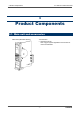
3 Product Components 3-1. Main unit and accessories 3 Product Components 3-1.
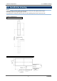
3 Product Components 3-2. Outline drawing 3-2. Outline drawing NOTE Install the buzzer unit in a single-unit case (option) or multi-unit case (option) before using it. This section explains using the single-unit case. For information on using the multi-unit case, see the operating manual of the multi-unit case.
3 Product Components 3-3. Installation drawing 3-3. Installation drawing NOTE Install the buzzer unit in a single-unit case (option) or multi-unit case (option) before using it. This section explains using the single-unit case. For information on using the multi-unit case, see the operating manual of the multi-unit case.
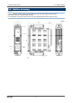
3 Product Components 3-4. Names and functions for each part 3-4. Names and functions for each part TAN-5000 (Self-latching type) TAN-5000L (Lock-in type) (4) Reset switch (5) Buzzer stop (check) switch (Only for lock-in type) (6) Buzzer opening (3) Fault lamp (2) Power lamp (1) Power switch (1) (2) (3) (4) (5) (6) Power switch (POWER): Power lamp (POWER): Fault lamp (FAULT): Reset switch (RESET): Buzzer stop switch (BUZZER STOP): Buzzer opening: TAN-5000 Power switch. Power lamp.
3 Product Components 3-5. Detaching and attaching the buzzer unit 3-5. Detaching and attaching the buzzer unit Detach or attach the buzzer unit from the single-unit case or multi-unit case according to the following procedure. (1) Attaching procedure • Open the front cover of the buzzer unit. • Make sure that the power switch of the buzzer unit is OFF. • Insert the buzzer unit along the rail into the single-unit case or multi-unit case.
3 Product Components 3-6. Block diagram 3-6.
4 How to Use 4-1. Before using the buzzer unit 4 How to Use 4-1. Before using the buzzer unit Not only the first-time users but also the users who have already used the product must follow the operating precautions. Ignoring the precautions may damage the buzzer unit, resulting in inaccurate gas detection. NOTE Install the buzzer unit in a single-unit case (option) or multi-unit case (option) before using it. This section explains using the single-unit case.
4 How to Use 4-3. Precautions for system designing Do not install the buzzer unit in a place where maintenance of the buzzer unit cannot be performed or where handling the buzzer unit involves dangers. Regular maintenance of the buzzer unit must be performed.
4 How to Use 4-3. Precautions for system designing Introducing protective measures against lightning If cables are installed outside the factory/plant, or if internal cables are installed in the same duct as the cables coming from outside the factory/plant, "lightning" will cause problems. Because lightning acts as a large emission source while cables act as a receiving antenna, devices connected to the cables may be damaged. Lightning cannot be prevented.
4 How to Use 4-4. How to wire If load is to be activated, appropriate measures must be taken to stabilize the operation of the buzzer unit and protect the alarm contact referring to the following information. • Relay it with an external relay at a lower voltage of 100 VAC or below (contact amplification). At the same time, the surge absorbing part SK1 suitable for the specifications must be attached to the external relay.
4 How to Use 4-4. How to wire NOTE Install the buzzer unit in a single-unit case (option) or multi-unit case (option) before using it. This section explains using the single-unit case. For information on using the multi-unit case, see the operating manual of the multi-unit case.
4 How to Use 4-4.
4 How to Use 4-4. How to wire Connection conditions • Cable: 0.08 - 2.5mm2 • Bare wire length: 8 - 9 mm • Connecting tools: Dedicated screwdrivers manufactured by WAGO and equivalent (edge width 3.5 mm x 0.5 mm or less) • Dedicated products 210-120J:.....Standard model 210-350/01:..Short model 210-258J:.....Angle model • When using a general-purpose screwdriver, use one with an edge width of from 2.5 mm to 3.5 mm.
4 How to Use 4-4. How to wire When cables are connected to the terminal plate, use the dedicated screwdriver or a compatible flathead screwdriver to do it as shown below. CAUTION The right tools must be used. Only one wire can be connected to one wiring hole. When the wire is inserted into the driver slot by mistake, it does not contact the conductive part. This may cause defective electric conduction or heating.
4 How to Use 4-5. Grounding 4-5. Grounding Connect the buzzer unit to your grounding terminal. WARNING Before turning on the buzzer unit, never fail to connect it to a grounding terminal. For stable operation of the buzzer unit and safety, it must be connected to a grounding terminal. Do not connect the grounding wire to a gas pipe. The grounding must be made as D type grounding (below 100 Ω of grounding resistance).
5 How to Operate 5-1. Preparation for start-up 5 How to Operate 5-1. Preparation for start-up Before supplying power, read and understand the following precautions. Ignoring these precautions may cause an electric shock or damage the buzzer unit. • • • • Connect the buzzer unit to a grounding circuit. Check that the wiring is connected to external device properly. Check that the power supply voltage is compliant with the specifications.
5 How to Operate 5-3. How to start the buzzer unit 5-3. How to start the buzzer unit • • • • Before turning on the power switch, check that the buzzer unit is installed properly. Open the front cover of the buzzer unit to find the power switch. Turn ON the power switch. The power lamp lights up and the operation is started.
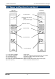
5 How to Operate 5-4. Description of operation 5-4. Description of operation 5-4-1. Common first and second alarm activation (1) Self-latching type The indicator/alarm unit outputs a gas alarm signal when the reading exceeds each of the gas alarm setpoints. The buzzer unit, when receiving this signal, sounds the buzzer and activates the common first and second alarm contacts. The buzzer and the common first and second alarm contacts are the self-latching type.
5 How to Operate Self-latching 5-4.
5 How to Operate 5-4.
5 How to Operate 5-5. Description of operation 5-5. Description of operation 5-5-1. How to change alarm contacts There are two types of alarm contacts: (1) Common first and second alarm contacts for gas alarm signals from the indicator/alarm unit and (2) Common fault alarm contacts for fault alarm signals. To change the settings of the contact specifications (such as the "a" or "b" contact), please contact RIKEN KEIKI. 5-5-2.
6 Measures for Abnormalities 5-5. Description of operation 6 Measures for Abnormalities The power lamp (green lamp) is off. • Fuse open-circuit • The cause can be either a failure of the buzzer unit or a failure of the external power supply. Find out the cause, take appropriate action, and then replace the fuse with a specified spare part.
7 Product Specifications 7-1. List of specifications 7 Product Specifications 7-1.
7 Product Specifications 7-1.
Warranty Policy RIKEN KEIKI CO., LTD., warrants gas alarm equipment sold by us to be free from defects in materials, workmanship, and performance for a period of one year from date of shipment from RIKEN KEIKI CO., LTD., Inc. Any parts found defective within that period will be repaired or replaced, at our option, free of charge.