Operator’s Manual SM-2009U Single Module Calibration Station Part Number: 71-0164RK Revision: A Released: 8/30/11 www.rkiinstruments.
Warranty RKI Instruments, Inc. warrants gas alarm equipment sold by us to be free from defects in materials and workmanship, and performance for a period of one year from date of shipment from RKI Instruments, Inc. Any parts found defective within that period will be repaired or replaced, at our option, free of charge.
Table of Contents Chapter 1: Introduction . . . . . . . . . . . . . . . . . . . . . . . . . . . . . . . . . . . . . . 1 Overview . . . . . . . . . . . . . . . . . . . . . . . . . . . . . . . . . . . . . . . . . . . . . . 1 About the SM-2009U . . . . . . . . . . . . . . . . . . . . . . . . . . . . . . . . . . . . . 1 System Requirements . . . . . . . . . . . . . . . . . . . . . . . . . . . . . . . . . . . . 2 Specifications. . . . . . . . . . . . . . . . . . . . . . . . . . . . . . . . . . . . . . . . . . .
Chapter 4: Using the SM-2009U. . . . . . . . . . . . . . . . . . . . . . . . . . . . . . . 25 Overview . . . . . . . . . . . . . . . . . . . . . . . . . . . . . . . . . . . . . . . . . . . . . 25 Bump Testing Instruments . . . . . . . . . . . . . . . . . . . . . . . . . . . . . . . . 25 Calibrating Instruments . . . . . . . . . . . . . . . . . . . . . . . . . . . . . . . . . . 31 Charging an Instrument in a Calibration Station . . . . . . . . . . . . . . . 35 Calibration and Bump Test Records . . . . . . .
Chapter 1: Introduction Overview This chapter briefly describes the SM-2009U Single Module Calibration Station and the Single Module Data View Software. This chapter also describes the SM-2009U Single Module Calibration Station Operator’s Manual (this document). Table 1 at the end of this chapter lists the SM-2009U’s specifications.
CAUTION: The GX-2009 detects oxygen deficiency and elevated levels of oxygen, combustible gases, carbon monoxide, and hydrogen sulfide, all of which can be dangerous or life threatening. When using the GX-2009, you must follow the instructions and warnings in the GX-2009 Operator’s Manual to assure proper and safe operation of the unit and to minimize the risk of personal injury.
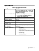
Specifications Table 1: SM-2009U Specifications Input Power 12 VDC NOTE: AC Adapter with 100 - 240 VAC, 50/ 60 Hz, 0.6A input and 12 VDC, 1.2A output provided as standard.
About this Manual The SM-2009U Single Module Calibration Stations Operator’s Manual uses the following conventions for notes, cautions, and warnings. NOTE: Describes additional or critical information. CAUTION: Describes potential damage to equipment. WARNING: Describes potential danger that can result in injury or death. Cautions & Safety Information • Use only polyurethane sample tubing with the SM-2009U. Consult RKI Instruments, Inc. for other materials.
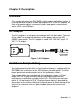
Chapter 2: Description Overview This section describes the SM-2009U single module calibration station. It is designed to be used on a table top and consists of the AC adaptor, air filter and sample tubing, instrument cradle, back panel, control panel, status LEDs, and USB port. AC Adapter The AC adapter is a wall plug style adapter with a 5 foot cable. The end of the cable has a plug that connects to the power jack on the SM2009U’s back panel. The AC adapter is rated 100 - 240 VAC input, 12 VDC 1.
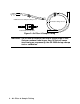
Calibration Gas Sample Tubing, 3 feet Exhaust Tubing, 10 feet Particle Filter for Air Inlet Figure 2: Air Filter & Sample Tubing WARNING: Do not use an exhaust tube that is longer than 10 feet. Using an exhaust tube longer than 10 feet will cause inaccurate gas response by the GX-2009 during a bump test or calibration.
Instrument Cradle The instrument cradle is a recessed area on the top of the SM-2009 that is designed to accept the GX-2009. Insert the GX-2009 in the instrument cradle when you perform a bump test or calibration. The cradle has charging contacts on the bottom that mate with the contacts on the back of the GX-2009. There are sample ports in the front of the cradle that match up with the GX-2009’s sensors and route air and calibration gas to the sensors during a bump test or calibration.
Back Panel The back panel includes the power jack and sample fittings. Exhaust Fitting CAL. GAS Fitting AIR Fitting Power Jack Figure 4: Back panel Power Jack The power jack is located in the lower left corner of the back panel. The plug on the end of the AC adapter cable mates to it. Sample Fittings Three sample fittings are located on the back of the SM-2009U. The AIR fitting is in the upper left corner and draws air into the SM-2009U. The CAL.
Control Panel The control panel is used to setup and operate the calibration station. It is located at the front of the calibration station. It includes the control buttons, the control button LEDs, and the CHARGE status LED. CHARGE LED COPY LED CAL. LED BUMP LED CHARGE GX-2009 OFF POWER BUMP CAL. EDIT ENTER COPY DATA CLEAR 1SEC ON 3SEC OFF Control Buttons Figure 5: Control Panel Five control buttons are located on the control panel. From left to right they are BUMP ▼, CAL.
Table 2: Control Button Functions Control Button Control Button LED Function(s) Control Button Function(s) BUMP ▼ • Initiates a bump test • Cancels a bump test • Moves down a list of parameters • Decreases an adjustable parameter Indicates status of a bump test in progress CAL.
Table 2: Control Button Functions Control Button POWER Control Button LED Function(s) Control Button Function(s) • Turns on the station • Turns off the station • Turns off connected GX-2009 (when used with EDIT ENTER button) n/a USB Port A USB port is located on the right front of the calibration station below the COPY and POWER buttons. The port can be used to save calibration and bump test data to a USB flash drive.
Chapter 3: Preparing to Use the SM-2009U Overview There are four tasks that must be completed before you can begin to use the SM-2009U: hardware assembly, setting the bump test and calibration parameters, connecting calibration gas, and installing the Single Module Data View Software on your computer. This chapter describes how to assemble the parts that are shipped with the SM-2009U and set the bump test and calibration parameters.
CAUTION: The maximum recommended length for the exhaust tube is 10 feet. Do not use more than 10 feet of tubing or tubing with an ID of less than 5/16” for the exhaust tube or the bump test and calibration accuracy will be adversely affected. The tube that is shipped with the SM-2009U has an ID of 5/16” and is 10 feet long. 6. Install the 3 foot long 3/16” ID tube that is included with the SM-2009U on the CAL. GAS fitting.
Table 3: Bump Test & Calibration Parameter Parameter Air Sample Time Display Tag Available Choices Bump Factory Setting Cal Factory Setting Air • • • • 30 seconds 45 seconds 60 seconds 90 seconds 30 seconds 45 seconds Calibration Gas Sample Time GAS • • • • • 30 seconds 45 seconds 60 seconds 90 seconds 120 seconds 30 seconds 90 seconds Bump Test Check Tolerance cHE • • • • • ± 10% ± 20% ± 30% ± 40% ± 50% 50% n/a Automatic Calibration cAL • On • Off Off n/a Air Sample Time (Air) Th
calibration gas through the CAL. GAS fitting on the back of the station during a bump test. Bump Test Check Tolerance (cHE) The bump test check tolerance only applies to bump testing. It determines how close the GX-2009 gas reading must be to the calibration gas concentration for each channel during a bump test in order to pass the bump test. It is defined as a percentage of the calibration gas concentration.
5. Install a GX-2009 in the instrument cradle. The CHARGE LED will begin to blink yellow. See “Charging an Instrument in a Calibration Station” on page 35 for a complete description of charging the GX2009. 6. Press and hold the POWER MODE button on the GX-2009 until you hear a beep, then release it. The GX-2009 will begin it’s power up sequence (see exceptions below in step 7). If a successful connection between the GX-2009 and the SM-2009U occurs, the TRANSMIT screen will appear on the GX-2009 display.
NOTE: You can still use the SM-2009 with an instrument for bump testing and calibration if this failure indication occurs, but you will not be able to perform any operations that require the display until a calibration is performed, the unit is turned off, and then the unit is re-connected to the SM-2009U. If you perform a bump test or calibration in this case, the only indication of pass or fail will be the BUMP or CAL. LED. • When Cal Limit Display is set to On and Cal.
2. Press and release the EDIT ENTER button. The GX-2009 will display the following screen. BUMP/CAL 3. Press and release the BUMP ▼ button. The GX-2009 will display the following screens alternating between the four bump test parameters and their settings. A ir cHE 30 50 GAS cAL BUMP 60 oFF BUMP 4. If you wish to cancel setting the bump test parameters or were just viewing the parameters to confirm their values, press and release the BUMP ▼ button to return to the TRANSMIT screen.
5. Use the BUMP ▼ and CAL. ▲ buttons to scroll through the parameters until the desired parameter is displayed. The scrolling sequence is shown below. Do not scroll past AUTO-C until you have finished making any desired changes. 60 30 AIR - IN GAS - IN oFF 50 CHECK AUTO - C 30 50 60 oFF DECISION CH4 %LEL OXY vol% 50 CO ppm 50 12.0 H2S ppm 25.0 TRANSMIT 6. With the desired parameter displayed, press and release the EDIT ENTER button.
7. Use the BUMP ▼ and CAL. ▲ buttons to set the parameter to the desired value, then press and release the EDIT ENTER button. The “E” next to the battery icon will disappear. 8. Repeat step 5 - step 7 to set any other parameters. 9. When you are done setting the parameters, use the BUMP ▼ button to scroll past AUTO-C. The DECISION screen will appear momentarily to indicate that the parameter changes have been saved and then the GX-2009 will return to the TRANSMIT screen.
To continue, press and release the EDIT ENTER button. The first parameter, air sample time, will be shown on the GX-2009 display. 30 AIR-IN 5. Use the BUMP ▼ and CAL. ▲ buttons to scroll through the parameters until the desired parameter is displayed. The scrolling sequence is shown below. Do not scroll past GAS-IN until you have finished making any desired changes. 60 30 AIR - IN GAS - IN 30 60 DECISION CH4 %LEL 50 50 CO ppm OXY vol% 12.0 H2S ppm 25.0 TRANSMIT 6.
7. Use the BUMP ▼ and CAL. ▲ buttons to set the parameter to the desired value, then press and release the EDIT ENTER button. The “E” next to the battery icon will disappear. 8. Repeat step 5 - step 7 to set any other parameters. 9. When you are done setting the parameters, use the BUMP ▼ button to scroll past GAS-IN. The DECISION screen will appear momentarily to indicate that the parameter changes have been saved and then the GX-2009 will return to the TRANSMIT screen. Connecting Calibration Gas The CAL.
Table 4: Recommended Gas Cylinders Typical Instrument Types Recommended Calibration Gas Cylinder Oxy/CO 3-gas mix with LEL/Oxy/CO Oxy/H2S 4-gas mix with LEL/Oxy/H2S/CO To connect calibration gas to the SM-2009U do the following: 1. If the area around the calibration station is not considered a fresh air area (an area free of combustible and toxic gases and of normal oxygen content, 20.
Installing the Single Module Data Viewer Software 1. Launch Windows®. 2. Exit from all applications and open windows. 3. Insert the Single Module Data Viewer Software Installation CD into your computer’s CD-ROM drive. 4. The Single Module Data Viewer InstallShield Wizard comes up to guide you through installation. Click Next to proceed to the License Agreement window. 5.
Chapter 4: Using the SM-2009U Overview When you have completed the tasks in "Chapter 3: Preparing to Use the SM-2009U", you are ready to use the SM-2009U calibration station. The SM-2009U is capable of performing bump tests and calibrations on the GX-2009. It can also charge the rechargeable batteries in the GX-2009. This chapter describes procedures for using the calibration station to bump test, calibrate, and recharge GX-2009s.
begin to blink yellow. If the batteries are fully charged, the CHARGE LED will become solid green after about 5 minutes. Typically a bump test or calibration will be initiated before this happens. See “Charging an Instrument in a Calibration Station” on page 35 for a complete description of charging the GX-2009.
connecting to the SM-2009U. FAIL C-LIMIT The failure screen will remain on the display while the unit is connected to the SM-2009U. NOTE: You can still use the SM-2009 with an instrument for bump testing and calibration if this failure indication occurs, but you will not be able to perform any operations that require the display until a calibration is performed, the unit is turned off, and then the unit is re-connected to the SM-2009U.
10. Press and hold the BUMP ▼ button for at least one second, then release it. The bump test begins. During the bump test, the BUMP LED will flash yellow indicating that a bump test is in progress and the GX-2009 display will show the current gas readings. CH4 %LEL 0 0 OXY vol% CO ppm 20.9 H2S ppm 0 BUMP 11. The SM-2009U will apply fresh air to the instrument for the time defined by the air sample time parameter. 12. The SM-2009U will perform a fresh air adjustment on the instrument. 13.
apply gas and perform a calibration. 16. The BUMP LED will stop blinking and be on steadily green if the bump test passed or steadily red if the bump test failed. 17. If the automatic calibration parameter is set to on and the instrument failed the bump test prompting an automatic calibration, the CAL. LED will be on steadily green if the calibration passed or steadily red if the calibration failed. 18. In addition to the indication by the BUMP LED and, if an automatic calibration took place, the CAL.
CH4 %LEL F P P P CO ppm OXY vol% P H2S ppm P P P CH4 %LEL LEL Failed Bump Test Calibration Passed BUMP/CAL CH4 %LEL OXY vol% P CO P ppm F P P H2S ppm P P P 50 50 CO ppm OXY vol% 12.0 H2S ppm 25.0 BUMP/CAL CH4 %LEL CO Failed Bump Test Calibration Passed BUMP/CAL 50 50 CO ppm OXY vol% 12.0 H2S ppm 25.0 BUMP/CAL Figure 8: Screen Indications for Bump Test & Automatic Calibration 19.
Calibrating Instruments When a calibration is performed, the calibration station performs a fresh air adjustment on an instrument and then applies calibration gas to the instrument. The calibration station analyzes the calibration results and determines if the instrument passed the calibration. To perform a calibration on an instrument: 1. Confirm that the AC Adapter is connected to the SM-2009U and to an AC wall socket. 2. Press and hold the SM-2009U’s POWER button.
NOTE: The screen shown above applies to a 4-channel GX-2009. If your GX-2009 has less than 4 channels, the inactive channels will not appear in the above screen and in any screens where channels are displayed. All screens in this manual assume a 4-channel GX-2009. 7. There are two exceptions to the sequence described in step 6 above. See the GX-2009 User Setup Program Operator’s Manual for a description of the Cal Limit Display and Cal Limit Check instrument parameters.
• When Cal Limit Display is set to On and Cal. Limit Check is set to Confirm to use, if the GX-2009 is due for calibration the unit will show the following screen and beep and flash the LED arrays for a few seconds indicating that calibration is due. CAL C--LIMIT When the beeping and flashing stops, press and release the POWER MODE button on the GX-2009 to continue.
failure and the following screen will appear. CH4 %LEL OXY vol% - -CO -ppm - - - - H2S- ppm- - - ZERO NG In this case you may attempt another bump test, press and release the EDIT ENTER button to return to the TRANSMIT screen, or turn off the GX-2009 using the EDIT ENTER and POWER buttons. 13. The SM-2009U will apply calibration gas to the instrument for the time defined by the calibration gas sample time parameter. 14.
17. The results of the calibration will be stored in the SM-2009U’s memory and will be available to copy to a USB flash drive. See “Copying Calibration and Bump Test Records to a USB Flash Drive” on page 37 for instructions to copy the saved bump test and calibration records to a USB flash drive. 18. If you wish to return to the Transmit screen, press and release the EDIT ENTER button. If not, continue with step 19. 19.
instrument by pressing and holding the EDIT ENTER and POWER buttons simultaneously for at least one second and then releasing them. If no buttons are pressed for 10 minutes, the calibration station will automatically turn off the instrument. 3. After a few seconds, the CHARGE LED will start blinking yellow. The BUMP and/or CAL. LED will continue to be either green or red depending on the result of the bump test or calibration. 4.
it, the CHARGE LED will continue to blink yellow while charging is taking place. The SM-2009U will take approximately 3 hours to charge a fully discharged GX-2009. 6. When the charge is complete, the CHARGE status LED will turn solid green. Calibration and Bump Test Records The SM-2009U saves a record of each bump test and calibration performed. It is capable of saving up to 200 such records. When an SM2009U’s memory becomes full, the oldest record is overwritten when a new record is saved.
NOTE: The USB port on the front of the calibration station cannot be used to connect the SM-2009U to a computer, only to save calibration and bump test records to a USB flash drive. 1. Confirm that the AC Adapter is connected to the SM-2009U and to an AC wall socket. 2. Press and hold the SM-2009U’s POWER button. The LEDs will turn amber and the internal pump will turn on momentarily. 3. When the pump stops and the BUMP and CAL. LEDs turn off, release the POWER button. 4.
NOTE: If you pull out the flash drive while it’s LED is still blinking and the COPY LED is still solid red, the file saved in the flash drive with the calibration and bump test records may be incomplete. 8. If the flash drive has not already been used with a calibration station, a folder named DAT will be created on the flash drive and a file with all the saved calibration and bump test records will be saved to this folder.
Bump Testing or Calibrating and Saving Files To a Flash Drive Multiple Times In One Day The SM-2009U assigns file names to calibration and bump test record files based on the day of the most recent calibration or bump test record saved in the calibration station’s memory.
Chapter 5: Single Module Data Viewer Program Overview The Single Module Data Viewer Program is used to view, organize, and print bump test and calibration records that were created by the SM2009U. It can also be used to export these records from it’s database for use in other programs. This chapter describes how to use the Single Module Data Viewer Program. Launching the Single Module Data Viewer Software 1. Click Start on the Windows® Icon Tray, then select Programs/ Single Module Data Viewer.
NOTE: When you start the Single Module Data Viewer Program for the first time, there will be no data in the left part of the data viewing window since no data has been imported into the database yet.
upper right side of the window shows the contents of the item selected in the upper left side, and the lower right side indicates the contents of the item selected in the area above it. In the example above, the data is organized by date. You can do the following in the data viewing window: • Import files into the database that were created by an SM-2009U • View the bump test and calibration data saved in the database. • Delete data. • Print bump test or calibration results (pass or fail indication only).
2. Navigate to the location of the files that you want to import into the database. 3. Select the files that you want to import. 4. Click the Apply button. A window will appear for a few seconds indicating that the file or files are being imported. 5. The files are now added to the database. Organizing the Data When viewing the data, it can be organized in two ways: 1.
2. ID View Format In ID view format, the data can be organized by one or more of the following items depending on which selection box or boxes in the lower left corner of the data viewing window are selected: • Serial Number • Station ID • User ID If any of these boxes is selected, the Base box disappears. The example below shows the data organized by serial number. Figure 14: Data in ID Viewing Format Viewing the Data Once you have selected how you want to organize the data: 1.
view the contents below it. Single click on an item to view the contents in the right side of the window. If an item is expanded and you want to close it, click the (-) symbol next to the item or double click it. 2. When an item no longer has a (+) or (-) symbol next to it, single click it and the contents of the item will be shown on the right side of the window. 3. If you are viewing data in base view format with the data organized by type, expand the item you wish to view, bump test or calibration data.
calibration or bump test files will appear in the upper right side of the window. If you are viewing data in ID view format, expand the folders in the left side of the window until the bump test or calibration folder you wish to view is visible. Expand the folder. Folders organized by year/month will be listed below the calibration or bump test folder. Click the folder whose contents you want to view and the calibration or bump test files in it will be shown in the upper right side of the data view window.
include the instrument’s serial number, station ID, user ID, bump test or calibration time, test gas, and gas readings during the operation. 6. To print the files as they appear in the upper right part of the data view window, click the print button in the upper left corner of the window. A dialog box will appear confirming if you want to print. Click OK. 7. To print only the pass or fail result of all files in the upper right window, click the Bump test & Calibration Report button above the files.
Deleting Data You can delete an instrument, bump test data, or calibration data in the data view window. The delete function is password protected to avoid accidental deletion of instruments or data. To delete an instrument or data, perform the following: 1. Find the item you wish to delete and right click it. A window will appear that says “Delete(D) Change Password(C)”. 2. Click on “Delete(D)”. A password entry window will appear. 3. Enter the password and click OK.
Exiting the Program To exit the Single Module Data View Program, do the following: 1. Click the Exit button in the upper right corner of the data view window. A confirmation window will appear. 2. Click the OK button to exit the program or the Cancel button to return to the program.
Table 6: Spare Parts List Part Number Description 81-0158RK-02 Four-gas calibration cylinder, 50% LEL Isobutane/12% O2/50 ppm CO/25 ppm H2S, 58 liter aluminum 81-0158RK-04 Four-gas calibration cylinder, 50% LEL Isobutane/12% O2/50 ppm CO/25 ppm H2S, 34 liter aluminum 81-1054RK Demand flow regulator, 58/103 liter cylinders 81-1055RK Demand flow regulator, for 17/34 liter steel cylinders 81-SM2009U Single Module Calibration Station for GX-2009 83-0009RK Single Mode Data Viewer software Spare Par