Operator’s Manual SM-2001U & SM-2003U Single Module Calibration Stations Part Number: 71-0130RK Revision: B Released: 6/17/10 www.rkiinstruments.
Warranty RKI Instruments, Inc., warrants gas alarm equipment sold by us to be free from defects in materials and workmanship, and performance for a period of one year from date of shipment from RKI Instruments, Inc. Any parts found defective within that period will be repaired or replaced, at our option, free of charge.
Table of Contents Warranty . . . . . . . . . . . . . . . . . . . . . . . . . . . . . . . . . . . . . . . . . . . . . . . . . . 2 Table of Contents . . . . . . . . . . . . . . . . . . . . . . . . . . . . . . . . . . . . . . . . . . . 3 Chapter 1: Introduction . . . . . . . . . . . . . . . . . . . . . . . . . . . . . . . . . . . . . . 5 Overview . . . . . . . . . . . . . . . . . . . . . . . . . . . . . . . . . . . . . . . . . . . . . . 5 About the SM-2001U & SM02003U. . . . . . . . . . . . . . . . . . . . . .
Calibration and Bump Test Records . . . . . . . . . . . . . . . . . . . . . . . . 33 Chapter 5: Single Module Data Viewer Software . . . . . . . . . . . . . . . . . 37 Overview . . . . . . . . . . . . . . . . . . . . . . . . . . . . . . . . . . . . . . . . . . . . . 37 Launching the Single Module Data Viewer Software. . . . . . . . . . . . 37 Using the Single Module Data Viewer Software . . . . . . . . . . . . . . . 38 Spare Parts List . . . . . . . . . . . . . . . . . . . . . . . . . . . . . . . . . . . .
Chapter 1: Introduction Overview This chapter briefly describes the SM-2001U and SM-2003U Single Module Calibration Stations and the Single Module Data View Software. This chapter also describes the SM-2001U & SM-2003U Single Module Calibration Stations Operator’s Manual (this document). Table 1 at the end of this chapter lists the specifications for the calibration stations.
CAUTION: The GX-2001 and GX-2003 detect oxygen deficiency and elevated levels of oxygen, combustible gases, carbon monoxide, and hydrogen sulfide, all of which can be dangerous or life threatening. When using the GX-2001 and GX2003, you must follow the instructions and warnings in the Operator’s Manual for each instrument to assure proper and safe operation of the unit and to minimize the risk of personal injury.
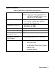
Specifications Table 1: SM-2001U & SM-2003U Specifications Input Power 100 VAC - 240 VAC, 50/60 Hz, 10 VA NOTE: The power cable supplied with the SM-2001U and SM-2003U as standard is for 115 VAC power.
About this Manual The SM-2001U & SM-2003U Single Module Calibration Stations Operator’s Manual uses the following conventions for notes, cautions, and warnings. NOTE: Describes additional or critical information. CAUTION: Describes potential damage to equipment. WARNING: Describes potential danger that can result in injury or death.
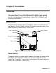
Chapter 2: Description Overview This section describes the SM-2001U and SM-2003U single module calibration stations. They are designed to be used on a table top and consist of the back panel, control panel, status LEDs, USB port, and instrument connections. Back Panel The back panels of both types of calibration stations are identical. The back panel is shown in Figure 1 below. It includes the power switch, fuse, power cord plug, sample fittings, and air filter. Exhaust Fittings CAL.
Fuse & Power Cord Plug A fuse holder is located to the right of the power switch. The fuse holder consists of a panel mounting socket and a quarter turn fuse holder. The fuse is a 2 amp, 5 mm x 20 mm fuse. A recessed 3-pin plug for the 115 VAC power cord is located to the right of the fuse holder. NOTE: Although the SM-2001U and SM-2003U can operate from 100 VAC - 240 VAC, the power cord supplied with the calibration stations is a 115 VAC power cord.
Control Panel, Status LEDs & USB Port The control panel and status LEDs are the same for both types of calibration stations. The control panel is used to setup and operate the calibration stations. It is located at the front of the calibration stations. It includes the MODE rotary switch, control buttons, and the control button LEDs. The CAL. and CHARGE status LEDs are located on the top front of the calibration stations. CAL. Status LED CAL.
Control Buttons & LEDs Four control buttons are located to the right of the MODE switch. From left to right they are BUMP, CAL., VOL., and COPY. Above each button is a control button LED that indicates the status of the function controlled by the button. . Table 2: Control Button Functions Control Button Control Button Function(s) Control Button LED Function(s) BUMP • Initiates a bump test • Cancels a bump test • Turns instrument off (when used with VOL.
Status LEDs Two status LEDs are located on the top front of the calibration stations. The CAL. status LED is on the left side of the station and indicates the status and result of a bump test or calibration. The CHARGE status LED is on the right side of the station and functions as a pilot LED, a system failure LED, and a charge indication LED. USB Port A USB port is located on the front right of the calibration station below the COPY button.
O2 F lo w RKI O2 O2 HC HC CO CO HC F lo w CO G X -2 0 01 M O DE D I SP A IR P OWE R H 2S H2 S H 2S SM-2001U SM-2001U OFF OFF MOD E MODE B UMP C AL. V OL. COPY CLEA R B UMP CAL. V OL. OP Y CLEA R Figure 3: SM-2001U Instrument Connections SM-2003U Instrument Connections The GX-2003 fits into the SM-2003U as shown in Figure 4 below. A coiled black tube with a plastic push-on fitting resides in a recess in the left rear corner of the top of the module.
NOTE: The SM-2003U is shipped with the green tube disassembled from the calibration station. See “Parts Assembly” on page 16 for assembly instructions. AIR DISPLAY (ADJ) POWER ENTER RESET SILENCE (SHIFT) SM-2003U SM-2003U OFF MOD E 9 0 1 8 7 2 6 5 4 3 BUMP CAL. VOL.
Chapter 3: Hardware Setup and Software Installation Overview There are two parts to preparing the SM-2001U and SM-2003U for use: hardware setup and software installation. This chapter describes how to setup the SM-2001U and SM-2003U hardware. It also describes how to install the Single Module Data Viewer Software on a Windows based personal computer.
Connecting an Exhaust Tube The top exhaust fitting port is used to route exhaust away from the calibration station. Install the 5/16” ID flexible tube that is included with the calibration station on the top exhaust fitting port and route the tube to an area where the calibration gas can be safely exhausted. CAUTION: The maximum recommended length for the exhaust tube is 10 feet.
Table 3: Recommended Gas Cylinders Typical Instrument Types Recommended Calibration Gas Cylinder(s) GX-2001 LEL/Oxy/H2S 4-gas mix with CH4/Oxy/H2S/CO GX-2003 GX-2003: LEL/Oxy H2S/CO 4-gas mix with CH4/Oxy/H2S/CO GX-2003 %Vol CH4/LEL CH4/Oxy/H2S/ CO • 4-gas mix with CH4/Oxy/H2S/CO • 100% Volume CH4 GX-2003 %Vol CH4/LEL CH4/Oxy/CO • 3-gas mix with CH4/Oxy/CO • 100% Volume CH4 GX-2003 LEL/Oxy/CO 3-gas mix with CH4/Oxy/CO GX-2003 LEL/Oxy/H2S 4-gas mix with CH4/Oxy/H2S/CO To connect calibration gas
that calibration gas is applied during a bump test, the shorter the bump test time, the larger bump test tolerance used to determine whether a bump test failed or passed. The MODE switch sets the value of the following bump test parameters: • Air Purge Time This is the length of time that a calibration station will draw air through the AIR fitting on the back of the station to an instrument installed in it.
The parameter settings for each MODE switch position are shown in Table 4 below. Table 4: MODE Switch Parameter Settings Switch Position Air Purge Time 0 Gas Exposure Time Tolerance 30 seconds ± 50% 1 ± 20% 45 Seconds 2 3 4 5 Auto. Cal.
Installing the Single Module Data Viewer Software 1. Launch Windows®. 2. Exit from all applications and open windows. 3. Insert the Single Module Data Viewer Software Installation CD into your computer’s CD-ROM drive. 4. The Single Module Data Viewer InstallShield Wizard comes up to guide you through installation. Click Next to proceed to the License Agreement window. 5.
Chapter 4: Using the SM-2001U & SM-2003U Overview The SM-2001U and SM-2003U calibration stations are capable of performing bump tests and calibrations on instruments and charging rechargeable battery packs in instruments. This chapter describes procedures for using the calibration stations to bump test, calibrate, and recharge GX-2001 and GX-2003 instruments. It also describes the information that is saved in a calibration station’s memory and how to save that information to a USB flash drive.
the inlet fitting, and then connect the plastic fitting on the end of the straight green tube to the exhaust fitting. If you take more than a few seconds before continuing, the CHARGE LED may begin blinking yellow indicating that the calibration station is charging the battery pack in the instrument if the instrument has a battery pack whose charge is low enough. 5. Turn on the instrument.
• Apply fresh air to the instrument for 30 seconds. • Perform a zero operation on the instrument. NOTE: If one or more of the sensors fails the zero operation, then the calibration station will abort the bump test and will not apply calibration gas. If this happens, the CAL. status LED will blink red indicating a failure and the BUMP control LED will stop blinking and be on steadily green. • Apply calibration gas to the instrument for the time defined by the MODE Switch setting.
CAUTION: When using the GX-2001 with the SM-2001U or the GX-2003 with the SM-2003U, do not turn off the instrument using the instrument power switch. Use the BUMP and VOL. control buttons on the calibration station to turn off the instrument. 14. Remove the instrument from the calibration station. Calibrating Instruments The SM-2001U and SM-2003U calibration stations are capable of performing a calibration on an instrument that is connected to it.
4. Turn on the instrument. • A GX-2003 will begin its normal startup sequence and after a few seconds, the pump will turn off and the display will indicate it is ready to communicate with the calibration station: PC TRANSMIT STAND BY OK 21:09 If LB Mode is activated on a GX-2003, press the POWER ENTER button as soon as the unit turns on to avoid waiting 20 seconds for the unit to time out of the Mode Select screen to begin its startup sequence.
NOTE: If one or more of the sensors fails the zero operation, then the calibration station will abort the calibration and will not apply calibration gas. If this happens, the CAL. status LED will blink red indicating a failure and the CAL. control LED will stop blinking and be on steadily green. • Apply calibration gas to the instrument for 90 seconds. • Purge the system with fresh air for 30 seconds. 8. After the system is purged, the CAL.
Bump Testing and Calibrating a GX-2003 with 100% Volume Methane The GX-2003 can have a %volume methane detector installed. This detector cannot be bump tested or calibrated using the typical gas mix that is used for the other detectors. To accommodate this special need, the SM-2003U includes the VOL. control button. This button activates the %volume gas function.
the back of the station. The CHARGE status LED will begin to blink green. 4. Put the GX-2003 to be bump tested or calibrated into the SM2003U, connect the plastic fitting on the end of the coiled black tube to the inlet fitting, and then connect the plastic fitting on the end of the straight green tube to the exhaust fitting.
following functions: • It will apply fresh air to the instrument for 30 seconds. • It will perform a zero operation on the GX-2003. NOTE: If the %volume methane detector fails the zero operation, then the calibration station will abort the bump test or calibration and will not apply calibration gas. If this happens, the CAL. status LED will blink red indicating a failure and the CAL. control LED will stop blinking and be on steadily green.
CAUTION: When using the GX-2001 with the SM-2001U or the GX-2003 with the SM-2003U, do not turn off the instrument using the instrument power switch. Use the BUMP and VOL. control buttons on the calibration station to turn off the instrument. 15. Remove the instrument from the SM-2003U. Charging an Instrument in a Calibration Station The SM-2001U and SM-2003U calibration stations can be used to charge the rechargeable battery pack in a GX-2001 or GX-2003.
4. If the battery pack is fully charged, then the CHARGE status LED will turn solid green in a few minutes. If the battery pack is drained enough for the calibration station to charge it, the CHARGE status LED will continue to blink yellow while charging is taking place. Both the GX-2001 and GX-2003 will take approximately 90 minutes to fully charge. 5. When the charge is complete, the CHARGE status LED will turn solid green.
Calibration and Bump Test Records The SM-2001U and SM-2003U save a record of each bump test and calibration performed. The calibration stations are capable of saving up to 200 such records. When a calibration station’s memory becomes full, the oldest record is overwritten when a new record is saved. These saved records can be saved to a USB flash drive using the USB port.
Copying Calibration and Bump Test Records to a USB Flash Drive The calibration station will only perform a copy operation if there is at least one record saved in it’s memory. If there are no records saved in the station’s memory, the COPY LED will be off and the COPY button will not function. Do the following to save calibration and bump test records in the calibration station’s memory to a USB flash drive. 1. If the calibration station is off, turn it on using the power switch on the back of the station.
4. Wait until the flash drive’s LED stops blinking, then remove the flash drive from the USB port. NOTE: If you pull out the flash drive while it’s LED is still blinking, the file saved in the flash drive with the calibration and bump test records may be incomplete. 5. If the flash drive has not already been used with a calibration station, a folder named DAT will be created on the flash drive and a file with all the saved calibration and bump test records will be saved to this folder.
Bump Testing or Calibrating and Saving Files To a Flash Drive Multiple Times In One Day The SM-2001U and SM-2003U assign file names to calibration and bump test record files based on the day of the most recent calibration or bump test record saved in the calibration station’s memory.
Chapter 5: Single Module Data Viewer Software Overview The Single Module Data Viewer Software is used to view, organize, and print bump test and calibration records that were created by the SM2001U and SM-2003U. It can also be used to export these records from it’s database for use in other programs. This chapter describes how to use the Single Module Data Viewer Software. Launching the Single Module Data Viewer Software 1.
NOTE: When you start the Single Module Data Viewer program for the first time, there will be no data in the left part of the data viewing window since no data has been imported into the database yet.
upper right side of the window shows the contents of the item selected in the upper left side, and the lower right side indicates the contents of the item selected in the area above it. In the example above, the data is organized by date. You can do the following in the data viewing window: • Import files into the database that were created by an SM-2001U or SM-2003U • View the bump test and calibration data saved in the database. • Delete data.
2. Navigate to the location of the files that you want to import into the database and select them. 3. Click the Apply button. A window will appear for a few seconds indicating that the file or files are being imported. 4. The files are now added to the database. Viewing the Data When viewing the data, it can be organized in two ways: 1.
2. ID View Format In ID view format, the data can be organized by one or more of the following items depending on which selection box or boxes in the lower left corner of the data viewing window are selected: • Serial Number • Station ID • User ID If any of these boxes is selected, the Base box disappears. The example below shows the data organized by serial number. Figure 9: Data in ID Viewing Format The data is organized in folders.
Once you have selected how you want to organize the data: 1. Click the expanded view symbol (+) next to a folder in the left side of the data viewing window or double click the folder to view the contents below it. Single click on the folder to view the contents in the right side of the window. If a folder is expanded and you want to close it, click the (-) symbol next to the folder or double click it. 2.
month appear in the left side of the window. Expand the folder you want to see and click on the calibration or bump test folder. The calibration or bump test files will appear in the upper right side of the window. If you are viewing data in ID view format, expand the folders in the left side of the window until the bump test or calibration folder you wish to view is visible. Expand the folder. Folders organized by year/month will be listed below the calibration or bump test folder.
the data view window that you wish to view. The contents in the file will appear in the lower right part of the window. The contents include the instrument’s serial number, station ID, user ID, bump test or calibration time, test gas, and gas readings during the operation. 6. To print the files as they appear in the upper right part of the data view window, click the print button in the upper left corner of the window. A dialog box will appear confirming if you want to print. Click OK. 7.
accidental deletion of instruments or data. To delete an instrument or data, perform the following: 1. Find the item you wish to delete and right click it. A window will appear that says “Delete(D) Change Password(C)”. 2. Click on “Delete(D)”. A password entry window will appear. 3. Enter the password and click OK. The default password is “ABCDE” and is case sensitive. A confirmation window will appear. 4. Click OK to complete the deletion of the selected item.
2. Click the OK button to exit the program or the Cancel button to return to the program.