SDM-2012 Docking Station Standalone Configuration Operator’s Manual Part Number: 71-0254RK Revision: 0 Released: 8/12/13 www.rkiinstruments.
Warranty RKI Instruments, Inc. warrants gas alarm equipment sold by us to be free from defects in materials and workmanship, and performance for a period of one year from date of shipment from RKI Instruments, Inc. Any parts found defective within that period will be repaired or replaced, at our option, free of charge.
Table of Contents Chapter 1: Introduction . . . . . . . . . . . . . . . . . . . . . . . . . . . . . . . . . . . . . . . . . . . . . . . . . 1 Overview . . . . . . . . . . . . . . . . . . . . . . . . . . . . . . . . . . . . . . . . . . . . . . . . . . . . . . . . 1 About the SDM-2012. . . . . . . . . . . . . . . . . . . . . . . . . . . . . . . . . . . . . . . . . . . . . . . 1 System Requirements. . . . . . . . . . . . . . . . . . . . . . . . . . . . . . . . . . . . . . . . . . . . . . 2 Specifications . . .
Setting the Gas Inlet for H2S (GX-2012 Only) . . . . . . . . . . . . . . . . . . . . . . . . . . . . . . . . . 26 Updating the Tested Sensors Setting . . . . . . . . . . . . . . . . . . . . . . . . . . . . . . . . . . . . . . . . 28 Connecting Calibration Gas . . . . . . . . . . . . . . . . . . . . . . . . . . . . . . . . . . . . . . . . 32 Installing the Single Module Data Viewer Software. . . . . . . . . . . . . . . . . . . . . . . 34 Chapter 4: Operation . . . . . . . . . . . . . . . . . . . . . . . . .
Deleting Data . . . . . . . . . . . . . . . . . . . . . . . . . . . . . . . . . . . . . . . . . . . . . . . . . . . . . . . . . 103 Changing the Password . . . . . . . . . . . . . . . . . . . . . . . . . . . . . . . . . . . . . . . . . . . . . . . . . 104 Exiting the Program . . . . . . . . . . . . . . . . . . . . . . . . . . . . . . . . . . . . . . . . . . . . . . . . . . . . 105 Spare Parts List . . . . . . . . . . . . . . . . . . . . . . . . . . . . . . . . . . . . . . . . . . . . . . . . . . . .
Chapter 1: Introduction Overview This chapter briefly describes the SDM-2012 Docking Station and the Single Module Data Viewer Program. This chapter also describes the SDM-2012 Docking Station Standalone Operation Operator’s Manual (this document). Table 1 at the end of this chapter lists the SDM-2012’s specifications.
CAUTION: The GX-2012 and Gas Tracer detect oxygen deficiency and elevated levels of oxygen, combustible gases, carbon monoxide, and hydrogen sulfide (GX-2012 only), all of which can be dangerous or life threatening. When using the GX-2012 or Gas Tracer, you must follow the instructions and warnings in the GX-2012 Operator’s Manual and/ or the Gas Tracer Operator’s Manual to assure proper and safe operation of the instrument and to minimize the risk of personal injury.
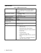
Specifications Table 1: SDM-2012 Specifications Input Power 12 VDC NOTE: AC Adapter with 100 - 240 VAC, 50/60 Hz, 0.6A input and 12 VDC, 1.2A output provided as standard.
About this Manual The SDM-2012 Docking Station Standalone Configuration Operator’s Manual uses the following conventions for notes, cautions, and warnings. NOTE: Describes additional or critical information. CAUTION: Describes potential damage to equipment. WARNING: Describes potential danger that can result in injury or death. Cautions & Safety Information • Use only polyurethane sample tubing with the SDM-2012. Consult RKI Instruments, Inc. for other materials.
Chapter 2: Description Overview This section describes the SDM-2012 docking station. It is designed to be used on a table top and consists of the AC adaptor, Type A to Type B USB cable, air filter, check valve, 3 plastic T-fittings, sample tubing, instrument panel, back panel, control panel, status LEDs, and 2 USB ports. AC Adapter Single-Port AC Adapter The single-port AC adapter is a wall plug style adapter with a 5 foot cable.
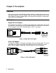
USB Cable A Type A to Type B USB cable is provided with the docking station. It is only for use with the PC Controlled configuration. It is not used in the Standalone configuration. Figure 3: USB Cable Air Filter and Sample Tubing A cylindrical particle filter with a short length of tubing is supplied with the SDM-2012 for installation to the AIR fitting on the back panel. The filter keeps particulate contamination out of the docking station.
A check valve is included with the SDM-2012 but is not needed for the Standalone configuration. It is used for the PC Controlled configuration. Figure 5: Check Valve Three T-fittings are included with the SDM-2012. The larger fitting is for the exhaust tubing. The smaller fittings are for GAS 1 and GAS 2 tubing. None of the T-fittings are needed for the Standalone configuration. They are used in the PC Controlled configuration.
Instrument Panel The instrument panel is on the top of the SDM-2012 and includes the instrument cradle, the IR port, the charging contacts, the exhaust line connection fitting, and the gas out to instrument line. The instrument cradle consists of two recessed areas and is designed to accept the instrument. The recess at the front of the instrument panel is for instruments that have a Li-ion battery pack installed. Charging contacts are located at the back of this recess.
Recess Cover Flap CHARGE GX-2012 OFF POWER BUMP EDIT ENTER CAL. COPY 1SEC ON 3SEC OFF SDM-2012 Figure 8: Instrument Panel with Alkaline Instrument Installed Recess Cover Flap CHARGE GX-2012 OFF POWER BUMP CAL.
Back Panel The back panel includes the power jack, sample fittings, and a USB PC connector. Exhaust Fitting Gas 1 Fitting Back Panel USB Port (Type B), For Computer Connection Air Fitting Power Jack Gas 2 Fitting Figure 10: Fittings and Connections Power Jack The power jack is located in the bottom left corner of the back panel. The plug on the end of the AC adapter cable mates to it. Sample Fittings Four sample fittings are located on the back of the SDM-2012.
Control Panel The control panel is used to setup and operate the docking station in the Standalone configuration. It is located at the front of the docking station. It includes the control buttons, the control button LEDs, and the CHARGE status LED. CHARGE LED COPY LED CAL LED BUMP LED CHARGE GX-2012 OFF POWER BUMP EDIT ENTER CAL. COPY 1SEC ON 3SEC OFF SDM-2012 Control Buttons Figure 11: Control Panel Five control buttons are located on the control panel.
Table 2: Control Button Functions Control Button Control Button LED Function(s) Control Button Function(s) CAL S • Initiates a calibration • Cancels a calibration • Clears data from docking station memory (when used with COPY button) • Moves up a list of parameters • Increases an adjustable parameter Indicates status of a calibration in progress EDIT ENTER • Puts docking station into various edit modes • Makes a displayed parameter editable • Escapes or cancels an operation • Turns off connected inst
Front Panel A type A USB port is located on the front of the docking station. This port can be used to save calibration and bump test data to a USB flash drive. This USB port is for use only in the Standalone configuration of the SDM-2012. Figure 12: Front Panel NOTE: The SDM-2012 does not support connection of a computer to the front USB port, only a USB flash drive.
Chapter 3: Preparing to Use the SDM-2012 Overview There are four tasks that must be completed before you can begin to use the SDM-2012: hardware assembly, setting or confirming the bump test and calibration parameters, connecting calibration gas, and installing the Single Module Data Viewer Software on your computer.
Step 1: Open End Open End Black Push On Fitting SDM-2012 Step 2: Black Push On Fitting CHARGE GX-2012 OFF POWER RKI Instruments, Inc. BUMP CAL. EDIT ENTER COPY www.rkiinstruments.com SDM-2012 1SEC ON 3SEC OFF Figure 13: Installing the Exhaust Line 5. Install the air filter so that the arrow on the filter that indicates direction of flow is pointing towards the AIR fitting. Push the open end of the flexible tube that is on one end of the filter onto the AIR fitting on the back of the SDM-2012.
Setting the Operational Parameters in Edit Mode Once the hardware has been assembled, use Edit Mode to confirm or adjust the bump test and calibration parameters, the H2S gas inlet parameter (GX-2012 only), and the WET/DRY setting (Gas Tracer only) before using the SDM-2012. The bump test parameters define how long fresh air and calibration gas are applied to an instrument during a bump test.
Table 3: Bump Test & Calibration Parameter Display Tag Parameter Available Choices Bump Test Check Tolerance CHE • • • • • ± 10% ± 20% ± 30% ± 40% ± 50% Automatic Calibration CAL • On • Off Bump Factory Setting Cal Factory Setting 50% n/a Off n/a Air Sample Time (AIR) The air sample time can be set separately for bump testing and calibration. It is the length of time that the SDM-2012 will draw air through the AIR fitting on the back of the docking station.
Turning on the SDM-2012 with an Instrument Do the following to turn on the SDM-2012 and establish a connection with an instrument: 1. Confirm that the AC Adapter is connected to the SDM-2012 and to an AC wall socket. 2. Press and hold the SDM-2012’s POWER button. The LEDs will turn amber. 3. When the BUMP T and CAL S LEDs turn off, release the POWER button. 4.
6. Press and hold the POWER ENTER button on the instrument until you hear a beep, then release it. The instrument will begin its power up sequence (see exceptions below in step 7). If a successful connection between the instrument and the SDM-2012 occurs, the home screen will appear on the instrument display at the end of the startup sequence. The heart symbol will be flashing and the combustible channel will scroll through the auto calibration values for all installed combustible gas sensors.
instrument is due for calibration, it will show a calibration expired failure screen and the buzzer and LED arrays will pulse. FAIL C--LIMIT The instrument will then connect to the SDM-2012 and display the home screen shown above in step 6. The CHARGE LED will begin to blink green. • When CL RMNDR is set to ON and CL EXPRD is set to CONFIRM, if the instrument is due for calibration, it will show the following screen and beep and flash the LED arrays for a few seconds indicating that calibration is due.
Setting the Bump Test Parameters Do the following to set the bump test parameters. 1. Turn on the SDM-2012 with an instrument and establish a connection between them as described above in "Turning on the SDM-2012 with an Instrument". The instrument will display the home screen. 50 O2 12.0 CO 50 H2 S 25.0 TRANSMIT CH4 2. %LEL % ppm ppm Press and hold the EDIT ENTER button for 2 seconds. The instrument will display the Edit Mode screen. B/C/E 3. Press and release the BUMP T button.
Parameters” on page 16. 30 AIR--IN 5. Use the BUMP T and CAL S buttons to scroll through the different bump test parameters.
6. To edit a parameter, press and release the EDIT ENTER button when that parameter is displayed. An “E” will appear to the left of the parameter name. 30 E AIR--IN 7. Use the BUMP T and CAL S buttons to set the parameter to the desired value, then press and release the EDIT ENTER button. The “E” to the right of parameter name will disappear. 8. Repeat step 6 - step 7 to set any other parameters. 9.
2. Press and hold the EDIT ENTER button for 2 seconds. The instrument will display the Edit Mode screen. B/C/E 3. Press and release the CAL S button. The instrument will alternate between the following screens that display the two calibration parameters and their settings. 45 90 AIr GAS CAL 4. CAL If you wish to cancel setting the calibration parameters or were just viewing the parameters to confirm their values, press and release the CAL S button to return to the home screen.
5. Use the BUMP T and CAL S buttons to scroll through the different calibration parameters. 90 GAS--IN 6. To edit a parameter, press and release the EDIT ENTER button when that parameter is displayed. An “E” will appear to the right of the parameter name. 45 E AIR--IN 7. Use the BUMP T and CAL S buttons to set the parameter to the desired value, then press and release the EDIT ENTER button. The “E” to the right of parameter name will disappear. 8.
Setting the Gas Inlet for H2S (GX-2012 Only) If you are using a separate calibration cylinder for the H2S channel, you may set which gas inlet that cylinder will use. RKI Instruments, Inc. recommends using a 4gas mix cylinder that contains H2S and setting this parameter to GAS 1 (factory setting). To change the gas inlet for the H2S channel: 1. Turn on the SDM-2012 with a GX-2012 and establish a connection between them as described above in "Turning on the SDM-2012 with an Instrument".
4. Press and release the EDIT ENTER button. The current gas inlet setting will be displayed. GAS 1 H2S--IN 5. To edit the gas inlet setting, press and release the EDIT ENTER button. An “E” will appear to the left of H2S--IN. GAS 1 E H2S--IN 6. Use the BUMP T and CAL S buttons to scroll between GAS1 and GAS2. 7. Once you have made your selection, press and release the EDIT ENTER button. The “E” to the left of H2S--IN will disappear. 8.
Updating the Tested Sensors Setting The tested sensors setting allows the user to control what sensors are tested during a bump test or calibration that is performed using the SDM-2012. If Std is selected, only the standard sensors will be tested during a bump test or calibration performed using the SDM-2012. For a GX-2012, only the LEL/O2/CO/H2S channels will be tested. For a Gas Tracer, only the LEL/O2/CO channels will be tested.
3. Press and release the EDIT ENTER button. The instrument will alternate between the following screens. The appearance of these screens will be affected by the type of instrument inserted in the SDM-2012.
4. Press and release the EDIT ENTER button. • If a GX-2012 is inserted, the current setting for the H2S inlet will be displayed. For instructions to change the H2S inlet setting, see “Setting the Gas Inlet for H2S (GX-2012 Only)” on page 26. GAS 1 H2S--IN Press and release the BUMP T button to display the current tested sensor setting. Std GAS Continue to step 5. • If a Gas Tracer is inserted, the current tested sensors setting will be displayed.
5. To edit the tested sensor setting, press and release the EDIT ENTER button. An “E” will appear to the left of GAS. Std E GAS 6. Use the BUMP T and CAL S buttons to toggle between Std and ALL. 7. Once you have made your selection, press and release the EDIT ENTER button. The “E” to the left of GAS will disappear. 8. Use the BUMP T button to scroll down past the tested sensor setting. The screen will indicate that the parameter changes have been saved.
Connecting Calibration Gas The GAS 1 and GAS 2 fittings on the back of the docking station are designed to be used with a calibration gas cylinder that is fitted with a demand flow regulator. The AIR fitting may be used with a demand flow regulator and a cylinder of zero emissions air, but this is not normally necessary since the docking station will generally be in a fresh air area.
Table 4: Recommended Gas Cylinders Typical Instrument Types Recommended Calibration Gas Cylinder(s) ppm CH4/LEL CH4/Oxy/CO (Gas Tracer) • 3-gas mix with CH4/Oxy/CO • 1000 ppm CH4 ppm CH4/LEL CH4/%vol CH4/Oxy/CO (Gas Tracer) • 3-gas mix with CH4/Oxy/CO • 1000 ppm CH4 • 100% volume CH4 To connect calibration gas to the SDM-2012, do the following: 1. If the area around the docking station is not considered a fresh air area (an area free of combustible and toxic gases and of normal oxygen content, 20.
Installing the Single Module Data Viewer Software 1. Launch Windows®. 2. Exit from all applications and open windows. 3. There are two ways to install the Single Module Data Viewer Software: by using the SDM-2012 product CD or by using the Single Module Data Viewer Software Installation CD. • If you are using the SDM-2012 Product CD, insert the Product CD into your computer’s CD-ROM drive. The CD will automatically open revealing several folders.
Chapter 4: Operation Overview When you have completed the tasks in "Chapter 3: Preparing to Use the SDM-2012", you are ready to use the SDM-2012 docking station. The SDM-2012 is capable of performing bump tests and calibrations on the GX-2012 and the Gas Tracer. It can also charge the optional rechargeable lithium ion battery pack in the instrument.
7. Connect the exhaust line to the exhaust fitting on the GX-2012.
8. Press and hold the POWER ENTER button on the GX-2012 until you hear a beep, then release it. The GX-2012 will begin its power up sequence (see exceptions below in step 9). If a successful connection between the instrument and the SDM-2012 occurs, the home screen will appear on the instrument display at the end of the startup sequence. The heart symbol will be flashing and the combustible channel will scroll through the auto calibration values for all installed combustible gas sensors.
• When CL RMNDR is set to ON and CL EXPRD is set to NOT USE, if the GX-2012 is due for calibration, the instrument will show a calibration expired failure screen and the buzzer and LED arrays will pulse. FAIL C--LIMIT The GX-2012 will then connect to the SDM-2012 and display the home screen shown above in step 8. The CHARGE LED will begin to blink green.
12. Press and hold the BUMP T button until the BUMP T LED turns on (about one second) then release it. During the bump test, the BUMP T LED will flash amber indicating that a bump test is in progress. 0 O2 20.9 CO 0 H2S 0.0 BUMP AIR CH4 0 O2 20.9 CO 0 H2S 0.
• If one or more of the sensors fails the fresh air adjustment, the SDM-2012 will abort the bump test and will not apply calibration gas. If this happens, the BUMP T LED will flash red indicating a failure and the following screen will appear indicating which channels passed and failed the fresh air adjustment with a P (pass) or an F (fail). In the following examples, the CO channel failed. CH4 O2 CO H2S ZERO P P F P NG 0 O2 20.9 CO 90 H2S 0.
17. The SDM-2012 will analyze the results. • If the bump test passes, continue with step 18. • If the bump test fails, and AUTO CAL is set to OFF, continue with step 18. • If the bump test fails, and AUTO CAL is set to ON, a calibration will automatically begin and calibration gas will continue to flow. The CAL S LED will begin to flash amber. NOTE: GAS 1 calibration gas will continue to be applied so that the total gas application time is the time defined by the GAS TIME calibration parameter.
• NOTE: If the bump test fails, and AUTO CAL was set to ON, a calibration will automatically begin and calibration gas will continue to flow. The CAL S LED will begin to flash amber. GAS 2 calibration gas will continue to be applied so that the total gas application time is the time defined by the GAS TIME calibration parameter. This time includes the time that the instrument was being bump tested.
21. After the fresh air purge is complete, the GX-2012 screen will alternate between the gas readings and the bump test or bump test and calibration results. For a successful bump test or calibration, the auto calibration values will be displayed. For a failed bump test or calibration, the gas readings at the end of the gas application will be displayed.
F F F F CH4 O2 CO H2S 12 18.0 7 13.5 CH4 %LEL % O2 ppm CO ppm H2S BUMP %LEL % ppm ppm BUMP Figure 20: Screen Indication for Failed Bump Test, AUTO CAL OFF, Standard 4-Gas GX-2012 or GAS Menu Item in Edit Mode Set to Std CH4 O2 CO H2 S F F F F O2 CO H2S BUMP vol% 10 vol% ppm ppm EDIT ENTER 12 18.0 7 13.
F P O2 F P CO F P H2S F P BUMP/CAL CH4 50 O2 12.0 CO 50 H2 S 25.0 BUMP/CAL CH4 %LEL % ppm ppm %LEL % ppm ppm Figure 22: Screen Indication for Failed Bump Test and Passed Auto Calibration, Standard 4-Gas GX-2012 or GAS Menu Item in Edit Mode Set to Std F P O2 F P CO F P H2 S F P BUMP/CAL CH4 CH4 %LEL vol% % ppm ppm EDIT ENTER 50 O2 12.0 CO 50 H2S 25.
F F O2 F F CO F F H2S F F BUMP/CAL CH4 10 O2 17.0 CO 30 H2 S 15.3 BUMP/CAL CH4 %LEL % ppm ppm %LEL % ppm ppm Figure 24: Screen Indication for Failed Bump Test and Failed Calibration, Standard 4-Gas GX-2012 or GAS Menu Item in Edit Mode Set to Std F F O2 F F CO F F H2 S F F BUMP/CAL CH4 CH4 %LEL F F vol% % ppm ppm BUMP/CAL EDIT ENTER 10 O2 17.0 CO 30 H2S 15.
pump starts. To perform a calibration, press and hold the CAL S button until the pump starts. To return to the home screen, press and hold the EDIT ENTER button until the home screen appears. • To turn the GX-2012 off: If the bump test was successful, the instrument will shut off after 15 seconds. If the bump test failed, the instrument will shut off after 10 minutes.
Calibrating a GX-2012 The following instructions apply to GX-2012s with one or more of the standard four sensors (catalytic LEL, O2, CO, and H2S). They also apply to GX-2012s with a %volume combustible sensor. See “Calibrating a Gas Tracer” on page 75 for instructions to calibrate a Gas Tracer. When a calibration is performed, the docking station performs a fresh air adjustment on an instrument and then applies calibration gas to the instrument.
7. Connect the exhaust line to the exhaust fitting on the GX-2012. GX-2012 or Gas Tracer with Alkaline Battery P ack GX-2012 or Gas Tracer with Li-Ion Battery P ack Figure 26: Inserting the GX-2012 8. Press and hold the POWER ENTER button on the GX-2012 until you hear a beep, then release it. The GX-2012 will begin its power up sequence (see exceptions below in step 9).
and the SDM-2012 occurs, the home screen will appear on the instrument display at the end of the startup sequence. The heart symbol will be flashing and the combustible channel will scroll through the auto calibration values for all installed combustible gas sensors. If you have a standard 4-channel GX2012, only the auto calibration value for the %LEL channel will be displayed. If the charge LED was amber, it will begin to blink green. 100 O2 12.0 CO 50 H2S 25.0 TRANSMIT CH4 NOTE: 9. vol% 50 O2 12.
• When CL RMNDR is set to ON and CL EXPRD is set to NOT USE, if the GX-2012 is due for calibration, the instrument will show a calibration expired failure screen and the buzzer and LED arrays will pulse. FAIL C--LIMIT The GX-2012 will then connect to the SDM-2012 and display the home screen shown above in step 8. The CHARGE LED will begin to blink green.
11. Press and hold the CAL S button until the CAL S LED turns on (about one second) then release it. During the calibration, the CAL S LED will flash amber indicating that a calibration is in progress. 0 O2 20.9 CO 0 H2S 0.0 CAL AIR CH4 0 O2 20.9 CO 0 H2S 0.
• If one or more of the sensors fails the fresh air adjustment, the SDM-2012 will abort the calibration and will not apply calibration gas. If this happens, the CAL S LED will flash red indicating a failure and the following screens will appear indicating which channels passed and failed the fresh air adjustment with a P (pass) or an F (fail). In the following examples, the CO channel failed the fresh air adjustment. CH4 O2 CO H2S ZERO P P F P NG 0 O2 20.9 CO 90 H2S 0.
menu item in Edit Mode is set to Std, continue with step 17. If a %volume sensor is installed in your GX-2012 and if the GAS menu item in Edit Mode is set to ALL, GAS 2 calibration gas will then be applied to that sensor for the time defined by the GAS TIME calibration parameter. CH4 98 vol% CAL G2 17. The SDM-2012 will then purge the system with fresh air for the time defined by the AIR TIME calibration parameter. CAL AIR 18.
P P F P CH4 O2 CO H2 S 49 O2 12.0 CO 12 H2S 24.5 CAL P vol% % ppm ppm CAL CH4 CH4 %LEL EDIT ENTER %LEL CAL CH4 98 vol% % ppm ppm CAL Figure 30: Calibration Results, %Volume Sensor Installed and GAS Menu Item in Edit Mode Set to ALL NOTE: If the GAS menu item in Edit Mode is set to Std, there will be no calibration results for the %volume sensor and pressing and releasing the EDIT ENTER button will have no effect. 19.
second and then release them. To avoid accidentally entering Edit Mode, press and hold the POWER button first, then press and hold the EDIT ENTER button. CAUTION: When using the GX-2012 with the SDM-2012, do not turn off the instrument using the instrument power button. Use the EDIT ENTER and POWER buttons on the SDM-2012 to turn off the instrument. The CAL S LED will remain on indicating the test results.
Bump Testing a Gas Tracer The following instructions apply to standard Gas Tracers that contain the standard sensors (catalytic LEL, ppm combustible, O2, and CO). They also apply to Gas Tracers that have a %volume combustible gas sensor installed. See “Bump Testing a GX-2012” on page 35 for instructions to bump test a GX-2012. When a bump test is performed, the SDM-2012 performs a fresh air adjustment on a Gas Tracer and then applies calibration gas to the instrument.
7. Connect the exhaust line to the exhaust fitting on the Gas Tracer. GX-2012 or Gas Tracer with Alkaline Battery P ack GX-2012 or Gas Tracer with Li-Ion Battery P ack Figure 31: Inserting the Gas Tracer 8. Press and hold the POWER ENTER button on the Gas Tracer until you hear a beep, then release it. The Gas Tracer will begin its power up sequence (see exceptions below in step 9).
charge LED was amber, it will begin to blink green. 100 O2 12.0 CO 50 H2 S 25.0 TRANSMIT CH4 NOTE: 9. vol% 50 O2 12.0 CO 50 H2S 25.0 TRANSMIT CH4 % ppm ppm %LEL % ppm ppm 1000 O2 12.0 CO 50 H2 S 25.0 TRANSMIT CH4 ppm % ppm ppm The screen above applies to a standard Gas Tracer with a %volume combustible gas sensor installed. All screens in this section will be shown for a standard Gas Tracer as well as a standard Gas Tracer with a %volume combustible gas sensor installed.
• When CL RMNDR is set to ON and CL EXPRD is set to NOT USE, if the Gas Tracer is due for calibration, the instrument will show a calibration expired failure screen and the buzzer and LED arrays will pulse. FAIL C--LIMIT The Gas Tracer will then connect to the SDM-2012 and display the home screen shown above in step 8. The CHARGE LED will begin to blink green.
NOTE: Do not use a 4-gas cylinder or any cylinder that includes H2S when bump testing a Gas Tracer. H2S adversely affects the ppm combustible sensor. 11. Press and hold the BUMP T button until the BUMP T LED turns on (about one second) then release it. During the bump test, the BUMP T LED will flash amber indicating that a bump test is in progress. If you wish to cancel the bump test, press and hold the BUMP T button for at least one second until CANCEL appears on the screen. 12.
14. Remove any connected cylinders and press and release the EDIT ENTER button. The SDM-2012 will purge for 30 seconds. PURGE 15. At the end of the purge cycle, you will be prompted to reconnect the calibration cylinder to the GAS 2 fitting. GAS2 On PURGE 16. Reconnect the ppm calibration cylinder and press and release the EDIT ENTER button. 17. The SDM-2012 begins the bump test by applying fresh air to the ppm sensor for the time defined by the AIR TIME bump test parameter.
• If the ppm sensor fails the fresh air adjustment, the SDM-2012 will abort the bump test and will not apply calibration gas. If this happens, the BUMP T LED will flash red indicating a failure and the following screens will alternate. CH4 ZERO F CH4 ppm NG 2500 ZERO ppm NG In this case continue with step 31. 19. The SDM-2012 will apply GAS 2 calibration gas to the ppm sensor for the time defined by the GAS TIME bump test parameter.
NOTE: GAS 2 calibration gas will continue to be applied so that the total gas application time is the time defined by the GAS TIME calibration parameter. This time includes the time that the instrument was being bump tested. If the GAS TIME calibration parameter is set to 90 seconds and the GAS TIME bump test parameter is set to 30 seconds, the instrument will sample gas for an additional 60 seconds if the bump test fails to bring the total exposure time to 90 seconds. CH4 9800 ppm B/CAL G2 21.
sensor. CH4 O2 CO 0 20.9 90 ZERO CH4 %LEL 1000 ppm % ppm BUMP NG EDIT ENTER CO P P F ZERO NG CH4 O2 P CH4 %LEL ppm % ppm BUMP Figure 32: Fresh Air Adjustment Fail, Standard Gas Tracer and GAS Menu Item in Edit Mode Set to ALL CH4 O2 CO ZERO 0 20.
In this case continue with step 31. NOTE: If the GAS menu item in Edit Mode is set to Std, there will be no fresh air adjustment result for the ppm combustible sensor and pressing and releasing the EDIT ENTER button will have no function. 23. The SDM-2012 will apply GAS 1 calibration gas to the standard three sensors for the time defined by the GAS TIME bump test parameter. CH4 O2 CO 45 10.0 47 %LEL % ppm BUMP G 1 24. The SDM-2012 will analyze the results.
25. If your Gas Tracer does not have a %volume sensor installed, or if the GAS menu item in Edit Mode is set to Std, continue with step 29. If a %volume sensor is installed in your Gas Tracer and if the GAS menu item in Edit Mode is set to ALL, the Gas Tracer screen will prompt you to change the calibration cylinder connected to the GAS 2 fitting on the back of the SDM2012. vol% CH4 GAS2 SET 26.
NOTE: GAS 2 calibration gas will continue to be applied so that the total gas application time is the time defined by the GAS TIME calibration parameter. This time includes the time that the instrument was being bump tested. If the GAS TIME calibration parameter is set to 90 seconds and the GAS TIME bump test parameter is set to 30 seconds, the instrument will sample gas for an additional 60 seconds if the bump test fails to bring the total exposure time to 90 seconds. CH4 98 vol% B/CAL G2 29.
30. After the fresh air purge is complete, the screen will alternate between the gas readings and the bump test or bump test and calibration results. The results are indicated with a P (pass) or an F (fail) to the left of the channel units. For a successful bump test or calibration, the auto calibration values will be displayed. For a failed bump test or calibration, the gas readings at the end of the gas application will be displayed.
CH4 O2 CO 50 12.0 50 % O2 CO EDIT ENTER P P P 1000 100 ppm vol% ppm BUMP CH4 CH4 %LEL BUMP CH4 %LEL % P P ppm vol% ppm BUMP BUMP Figure 35: Successful Bump Test, %Volume Sensor Installed and GAS Menu Item in Edit Mode Set to ALL CH4 O2 CO 50 10.
50 10.0 5 CH4 O2 CO 800 98 CH4 %LEL % ppm vol% ppm BUMP BUMP EDIT ENTER P P F CH4 O2 CO F P CH4 %LEL % ppm vol% ppm BUMP BUMP Figure 37: Failed Bump Test, AUTO CAL OFF, %Volume Sensor Installed and GAS Menu Item in Edit Mode Set to ALL 50 12.
50 12.0 50 CH4 O2 CO CH4 %LEL % 1000 100 ppm vol% ppm BUMP BUMP EDIT ENTER CH4 O2 CO F F F P P P CH4 %LEL % F F P P ppm vol% ppm BUMP BUMP Figure 39: Failed Bump Test and Passed Calibration, %Volume Sensor Installed and GAS Menu Item in Edit Mode Set to ALL 20 17.
20 17.0 35 CH4 O2 CO 500 65 CH4 %LEL % ppm vol% ppm BUMP BUMP EDIT ENTER CH4 O2 CO F F F F F F %LEL % CH4 F F F F ppm vol% ppm BUMP BUMP Figure 41: Failed Bump Test and Calibration, %Volume Sensor Installed and GAS Menu Item in Edit Mode Set to ALL NOTE: If the GAS menu item in Edit Mode is set to Std, there will be no bump test or calibration results for the ppm combustible sensor or the %volume sensor and pressing and releasing the EDIT ENTER button will have no effect. 31.
hold the EDIT ENTER and POWER buttons simultaneously for about one second and then release them. To avoid accidentally entering Edit Mode, press and hold the POWER button first, then press and hold the EDIT ENTER button. CAUTION: When using the Gas Tracer with the SDM-2012, do not turn off the instrument using the instrument power button. Use the EDIT ENTER and POWER buttons on the SDM-2012 to turn off the instrument. The BUMP T LED or BUMP T LED and CAL S LED will remain on indicating the test results.
Calibrating a Gas Tracer The following instructions apply to standard Gas Tracers that contain the standard sensors (catalytic LEL, ppm combustible, O2, and CO). They also apply to Gas Tracers that have a %volume combustible gas sensor installed. See “Calibrating a GX-2012” on page 48 for instructions to calibrate a GX-2012. When a calibration is performed, the docking station performs a fresh air adjustment on an instrument and then applies calibration gas to the instrument.
7. Connect the exhaust line to the exhaust fitting on the Gas Tracer.
8. Press and hold the POWER ENTER button on the Gas Tracer until you hear a beep, then release it. The Gas Tracer will begin its power up sequence (see exceptions below in step 9). If a successful connection between the instrument and the SDM-2012 occurs, the home screen will appear on the instrument display at the end of the startup sequence. The heart symbol will be flashing and the combustible channel will scroll through the auto calibration values for all installed combustible gas sensors.
• When CL RMNDR is set to ON and CL EXPRD is set to NOT USE, if the Gas Tracer is due for calibration, the instrument will show a calibration expired failure screen and the buzzer and LED arrays will pulse. FAIL C--LIMIT The Gas Tracer will then connect to the SDM-2012 and display the home screen shown above in step 8. The CHARGE LED will begin to blink green.
NOTE: Do not use a 4-gas cylinder or any cylinder that includes H2S when calibrating a Gas Tracer. H2S adversely affects the ppm combustible sensor. 11. Press and hold the CAL S button until the CAL S LED turns on (about one second) then release it. During the calibration, the CAL S LED will flash amber indicating that a calibration is in progress. If you wish to cancel the calibration, press and hold the CAL S button for at least one second until CANCEL appears on the screen. 12.
14. Remove any connected cylinders and press and release the EDIT ENTER button. The SDM-2012 will purge for 30 seconds. PURGE 15. At the end of the purge cycle, you will be prompted to reconnect the calibration cylinder to the GAS 2 fitting. GAS2 On PURGE 16. Reconnect the ppm calibration cylinder and press and release the EDIT ENTER button. 17. The SDM-2012 begins the calibration by applying fresh air to the ppm sensor for the time defined by the AIR TIME calibration parameter.
• If the ppm sensor fails the fresh air adjustment, the SDM-2012 will abort the calibration and will not apply calibration gas. If this happens, the CAL S LED will flash red indicating a failure and the following screens will alternate. CH4 ZERO F CH4 ppm NG 2500 ZERO ppm NG In this case continue with step 28. 19. The SDM-2012 will apply GAS 2 calibration gas to the ppm sensor for the time defined by the GAS TIME calibration parameter.
• If one or more of the sensors fails the fresh air adjustment, the SDM-2012 will abort the calibration and will not apply calibration gas. If this happens, the CAL S LED will flash red indicating a failure and the Gas Tracer will alternate between the following screens. Use the EDIT ENTER button to scroll between the fresh air adjustment results for the standard three sensors and the calibration results for the ppm sensor. CH4 O2 CO ZERO CH4 O2 CO ZERO 0 20.
0 20.9 90 CH4 O2 CO ZERO vol% %LEL CH4 800 ppm % ppm NG CAL EDIT ENTER vol% %LEL CO P P F ZERO NG CH4 O2 CH4 F ppm % ppm CAL Figure 44: Failed Fresh Air Adjustment, %Volume Sensor Installed and GAS Menu Item in Edit Mode Set to ALL NOTE: If the GAS menu item in Edit Mode is set to Std, there will be no fresh air adjustment result for the ppm combustible sensor and pressing and releasing the EDIT ENTER button will have no effect. In this case continue with step 28. 22.
23. If your Gas Tracer does not have a %volume sensor installed, or if the GAS menu item in Edit Mode is set to Std, continue with step 26. If a %volume sensor is installed in your Gas Tracer and if the GAS menu item in Edit Mode is set to ALL, the Gas Tracer screen will prompt you to change the calibration cylinder connected to the GAS 2 fitting on the back of the SDM-2012. vol% CH4 GAS2 SET 24.
27. After the fresh air purge is complete, the screen will alternate between the gas readings and the calibration results. The calibration results are indicated with a P (pass) or an F (fail) to the left of the channel units. If the calibration passed, the auto calibration values will be displayed. If the calibration failed, the gas readings at the end of the gas application will be displayed.
50 10.0 5 CH4 O2 CO CH4 %LEL % 800 98 ppm vol% ppm CAL CAL EDIT ENTER P P F CH4 O2 CO %LEL CH4 % F P ppm vol% ppm CAL CAL Figure 46: Calibration Results, %Volume Sensor Installed and GAS Menu Item in Edit Mode Set to ALL NOTE: If the GAS menu item in Edit Mode is set to Std, there will be no calibration results for the ppm combustible sensor or the %volume sensor and pressing and releasing the EDIT ENTER button will have no effect. 28.
To turn off the instrument before it is automatically turned off, press and hold the EDIT ENTER and POWER buttons simultaneously for about one second and then release them. To avoid accidentally entering Edit Mode, press and hold the POWER button first, then press and hold the EDIT ENTER button. CAUTION: When using the Gas Tracer with the SDM-2012, do not turn off the instrument using the instrument power button. Use the EDIT ENTER and POWER buttons on the SDM-2012 to turn off the instrument.
Troubleshooting NOTE: This troubleshooting guide describes SDM-2012 problems only. See the GX-2012 Operator’s Manual or Gas Tracer Operator’s Manual for problems you may encounter with the instrument. Table 5: Troubleshooting the SDM-2012 Symptoms Probable Causes Recommended Action • Fresh air adjustment fails • The SDM-2012 is not in a fresh air environment or the cylinder being used is not a zero air cylinder. • If a zero air cylinder is used, the calibration cylinder is out of gas.
• No IR connection between instrument and SDM-2012 • SDM-2012 is not turned on. • The instrument is not correctly inserted into the instrument cradle. • The IR window is dirty. 1. Turn on the SDM-2012. If it does not turn on, check that the AC adapter is plugged into an AC socket and to the jack on the back of the SDM-2012. 2. Check to make sure the instrument is inserted properly. 3. Clean the IR window on the SDM-2012. 4. If the difficulties continue, contact RKI Instruments, Inc.
Charging an Instrument in a Docking Station The SDM-2012 can be used to charge the rechargeable Li-ion battery pack in an instrument equipped with it. To maximize the instrument’s run time and the battery life, make sure the battery pack’s charge is as low as possible before recharging it. Recharging a Battery Pack After Performing a Bump Test or Calibration 1.
Recharging a Battery Pack Without Performing Any Operations 1. Confirm that the AC adapter is connected to the back panel of the SDM-2012 and to an AC wall socket. 2. Insert the instrument or battery pack into the front recess of the instrument cradle. Battery Pack CHARGE GX-2012 OFF POWER BUMP CAL. SDM-2012 EDIT ENTER COPY 1SEC ON 3SEC OFF Figure 47: Inserting the Battery Pack for Charging 3. Press and hold the SDM-2012’s POWER button. The LEDs will turn amber. 4.
will go into a 5 minute charge cycle and the following screen will be displayed on the instrument screen. 04.59 CHARGING It will not connect to the docking station. The instrument cannot be bump tested or calibrated in the charge cycle. Once the 5 minute charge cycle has ended, the unit will automatically turn back on and connect to the docking station. The unit can now be bump tested or calibrated. Calibration and Bump Test Records The SDM-2012 saves a record of each bump test and calibration performed.
NOTE: The USB port on the front of the docking station cannot be used to connect the SDM-2012 to a computer, only to save calibration and bump test records to a USB flash drive. 1. Confirm that the AC Adapter is connected to the SDM-2012 and to an AC wall socket. 2. Press and hold the SDM-2012’s POWER button. The LEDs will turn amber. 3. When the BUMP T and CAL S LEDs turn off, release the POWER button. 4. The COPY LED will be off or on steadily and the CHARGE LED will be blinking green.
"Bump Test and Calibration Record Files" below for a discussion of these files and how to use them. Clearing the SDM-2012’s Memory Make sure that you save the bump test and calibration records in the SDM-2012’s memory to a flash drive before clearing its memory. The docking station’s memory can be cleared by simultaneously pressing and holding the CAL S and COPY buttons for five seconds. After the SDM-2012’s memory has been cleared, the COPY LED will turn off indicating there are no records to be copied.
Chapter 5: Single Module Data Viewer Program Overview The Single Module Data Viewer Program is used to view, organize, and print bump test and calibration records that were created by the SDM-2012 while used in the standalone configuration. It can also be used to export these records from its database for use in other programs. This chapter describes how to use the Single Module Data Viewer Program. Launching the Single Module Data Viewer Program 1.
NOTE: When you start the Single Module Data Viewer Program for the first time, there will be no data in the left part of the data viewing window since no data has been imported into the database yet.
• View the bump test and calibration data saved in the database. • Delete data. • Print bump test or calibration results (pass or fail indication only). • Copy bump test or calibration records to the clipboard or to a particular location on your computer or network. • Print a bump test or calibration report that includes the results and all gas readings.
Organizing the Data When viewing the data, it can be organized in two ways: 1. Base View Format In base view format, neither of the Serial No, Station ID, or User ID selection boxes in the lower left of the window are selected and the Base box appears next to these selection boxes with two radio buttons. The data can be organized by either the data Type (bump test and calibration data) or by Date (year and month). The example below shows the data organized by Type.
2. ID View Format In ID view format, the data can be organized by one or more of the following items depending on which selection box or boxes in the lower left corner of the data viewing window are selected: • Serial Number • Station ID • User ID If any of these boxes is selected, the Base box disappears. The example below shows the data organized by serial number. Figure 52: Data in ID Viewing Format Viewing the Data Once you have selected how you want to organize the data: 1.
2. When an item no longer has a (+) or (-) symbol next to it, single click it and the contents of the item will be shown on the right side of the window. 3. If you are viewing data in base view format with the data organized by type, expand the item, bump test or calibration, you wish to view. Icons organized by year/month will appear below the bump test or calibration icon. Click on the item whose contents you wish to see.
If you organize the data by date, then folders organized by year/month appear in the left side of the window. Expand the folder you want to see and click on the calibration or bump test folder. The calibration or bump test files will appear in the upper right side of the window.
If you are viewing data in ID view format, expand the folders in the left side of the window until the bump test or calibration folder you wish to view is visible. Expand the folder by clicking the (+) symbol next to it. Folders organized by year/month will be listed below the calibration or bump test folder. Click the folder whose contents you want to view and the calibration or bump test files in it will be shown in the upper right side of the data view window.
appear showing the selected printer and confirming if you want to print. Verify that the selected printer is correct and click OK. 8. To print the complete results, pass/fail and gas readings, of one of the files in the upper right part of the data view window, click on one of the files to select it and then click the print button that appears above the file details in the lower right. A dialog box will appear showing the selected printer and confirming if you want to print.
3. Enter the password and click OK. The factory set password is “ABCDE” and is case sensitive. A confirmation window will appear. 4. Click OK to complete the deletion of the selected item. Changing the Password The factory password is “ABCDE” and is case sensitive. You can change the password in the data view window. To change the password perform the following: 1. Right click in the upper right or upper left part of the data view window. A window will appear that says “Delete(D) Change Password(C)”.
4. Enter the new password and click the New Password button. A confirmation window will appear prompting you for the new password again. 5. Enter the new password again and click the Confirm New Password button. A window will appear indicating that the password has been changed. 6. Click OK to complete the password update. Exiting the Program To exit the Single Module Data Viewer Program, do the following: 1. Click the Exit button in the upper right corner of the data view window.
Table 7: Spare Parts List Part Number Description 33-2001RK-01 6 inch humidifier tube, for connecting ppm calibration cylinder to GAS 2 fitting and zero air cylinder (if used for WET fresh air adjustment) to AIR fitting 49-0115RK Single-port AC adapter 49-2058RK-03 3-port AC adapter 71-0254RK Operator’s Manual, SDM-2012 Docking Station Standalone Configuration (this document) 71-0256RK Operator’s Manual, SDM-2012 Docking Station PC Controller Configuration 71-8007RK Product CD for SDM-GX Series
Table 7: Spare Parts List Part Number Description 81-0154RK-04 Four-gas calibration cylinder, 50% LEL CH4/12% O2/50 ppm CO/ 25 ppm H2S, 34 liter aluminum 81-0158RK-02 Four-gas calibration cylinder, 50% LEL Isobutane/12% O2/50 ppm CO/25 ppm H2S, 58 liter aluminum 81-0158RK-04 Four-gas calibration cylinder, 50% LEL Isobutane/12% O2/50 ppm CO/25 ppm H2S, 34 liter aluminum 81-1054RK Demand flow regulator, 58/103 liter cylinders 81-1055RK Demand flow regulator, for 17/34 liter steel cylinders 81-SDM2