PT2E-1140 OPERATING INSTRUCTION MANUAL FOR SMART GAS DETECTOR/TRANSMITTER MODEL SD-705EC FOR USERS Safety Precautions 1. Read and understand the instructions in this manual before operating this instrument. 2. Keep manual accessible at all times. 3. This instrument cannot be used for any other purpose than what is specified in this manual. 4. Follow all the instructions in this manual, an deviation will compromise the safety, quality and performance of this instrument. 5.
PT2E-1140 Introduction Thank you for purchasing our fixed type gas detector/transmitter Model SD-705EC. This is a gas detector to detect toxic gases leaking into the atmosphere and transmit its signal to the central monitoring station to prevent accident caused by gas toxicity. This manual is a guidebook for use of the SD-705EC. All persons who use this detector for the first time and who has ever used the detector are requested to read through the manual to understand the content before use.
PT2E-1140 Contents 1.Functions of‥‥‥‥‥‥‥‥‥‥‥‥‥‥‥‥‥‥‥‥‥‥‥‥‥ 3 2.Handling 2ー1 Before Initial Use‥‥‥‥‥‥‥‥‥‥‥‥‥‥‥‥‥‥‥‥ 6 2−2 Cautions for installation and handling‥‥‥‥‥‥‥‥‥‥‥‥ 6 2−3 Caution for System Engineering‥‥‥‥‥‥‥‥‥‥‥‥‥‥‥ 7 2−4 Maintenance Space‥‥‥‥‥‥‥‥‥‥‥‥‥‥‥‥‥‥‥‥ 8 2−5 Installation Method‥‥‥‥‥‥‥‥‥‥‥‥‥‥‥‥‥‥‥… 9 2−6 Wiring Method‥‥‥‥‥‥‥‥‥‥‥‥‥‥‥‥‥‥‥‥‥‥ 13 3.Operation 3−1 Startup Method ‥‥‥‥‥‥‥‥‥‥‥‥‥‥‥‥‥‥‥‥‥ 16 3−2 Warm-up‥‥‥‥‥‥‥‥‥‥‥‥‥‥‥‥‥‥‥‥‥‥‥… 16 3−3 Detection Method‥‥‥‥‥‥‥‥‥‥‥‥‥‥‥‥‥‥‥‥ 17 3−4 Gas Alar
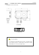
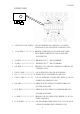
1.Function of the Product ◇ Overall view and name of each part 〔SD-705EC〕 △警告“強力磁石” △WARNING:MAGNET MODEL TC-7 RIKEN KEIKI 〔Control Key〕 ! WARNING The control key used for adjustment is made from a powerful magnet. If it is brought nearer to a credit card, ID card, other magnetic products, this key may damage the stored data.
PT2E-1140 Display Part ① MAINTENANCE/ESC switch‥‥Used for entering into the maintenance mode with the control key. And used for cancel the maintenance mode. ② PW/TR light‥‥……………… Illuminates continuously when the equipment is working (power light). And flickers in the case of abnormality in the equipment. ③ AL1 light ……………………‥‥ Illuminates when 1st alarm is activating. ④ AL2 light …………………‥‥ ⑤ SKIP light…………………‥‥ Illuminates when 2nd alarm is activating. Illuminated when point skip is selected.
PT2E-1140 Internal View ①Terminal plate………………… Connected to power source and 4-20mA signal output. ②Fuse…………………………… Fuse for power(0.5A) ③Rely output terminal………… Connected to alarm relay output cable. ④Earth terminal………………… Used to make grounding ⑤Cable inlet…………………… Used to lead the cable from the indicating alarm unit (With the pressure proof packing gland) ⑥Relay output and ………………Used to lead the cable from alarm relay output.
PT2E-1140 2.Handling 2−1 Before Initial Use On detecting a toxic gas leakage, this unit show the gas concentration on the LCD and outputs the gas concentration value in 4-20mA to the indicating alarm unit. When the concentration exceeds the preset level, the alarm contact activates. In view of its duty, the gas detector must always be in the normal operation with the power supply ON. Therefore, it is essential to confirm its operation daily.
PT2E-1140 ! Caution Be sure to use an optional drip-proof cover when the detector is to be installed out of doors. ⑤ Place where the temperature is below ‐10℃ or +40℃ or more ! CAUTION When intending to open the lid, wait for 30 seconds or more after powered OFF and then, open the lid. 2−3 Cautions for System Engineering Unstable power supply and noise may cause error of performance and alarm. For the system to use this detector, it is required to make design based on this manual description.
PT2E-1140 ② Power cable noise Following is available to reduce the influence of electromagnetic induction noise and electrostatic induction noise from power cable. Use signal cable with a shield and ground. Make electrical isolation such as using metal installation pipe for power cable, installing Isolation plate between power cable and electrostatic shield, and install them into exclusive metallic duct. (3) Grounding the instrument Lightning(Thunder) and etc make surge noise.
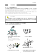
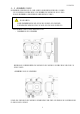
PT2E-1140 2−5 Installation Method (1) Install the detector body to a firm surface (wall surface, etc.) with M6 bolts. Use an optional mounting piece when installing the detector to the 2B pipe. (For the installation method, refer to Fig.1 through 4 below) ! CAUTION During installation, take care not to drop or throw the detector. Otherwise, the strong impact may cause damage to the equipment (a) Installation without using drip-proof cover ・ Installation to the wall (Fig.
PT2E-1140 (b) Installation using a drip-proof cover(option) When installing the cover, slide it from the top to downward along the groove and fix it with the bottom fixture. ・Installation to the wall(Fig.3) Install to the wall after fixing the detector to the detector mounting piece with screw as shown above. ・Installation to the 2B pipe(Fig.4) Secure the detector to the detector mounting piece with screw and fix it to the U-bolt(M10) for 2B pipe as shown above.
PT2E-1140 (2) Insert a packing gland(lower) →washer→packing→packing grand(upper) in this order onto the cable. Lead the cable into the detector terminal box and attach a stick-type crimp terminal plate to the end of cable. Cable finish O.D. Packing inside diameter(㎜) Washer inside diameter(㎜) φ11 ∼ 12 φ12 φ13 If cable finish O.D. does not meet with above packing gland, please contact with us.
PT2E-1140 ・For connection of terminal plate <In case of direct connection> Peel length of cable end:7 mm(3p terminal), 7mm(6p terminal) ※Do not make preliminary solder. <In case of using the compressed ground terminal> Bar terminal : Model Al series(Maker : Phoenix Contact) Terminal lug terminal : Model CRIMPFOX UD6(Maker : Phoenix Contact) ・Torque for terminals Torque:0.5∼0.6 Nm(3p terminal), 0.2∼0.
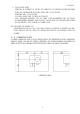
PT2E-1140 2−6 Wiring Method (1) After installation of detector, confirm that there is no error in installation, and carry out connection between equipment as follows. ① Connection of the SD−705EC to the indicating alarm section(EC−583etc.) Indicator 指 示警報部 EC-583 EC-583 SD-705EC DC24V Power input + − Sig 3 入力電源 DC24V(single case) 4 DC24V(シングルケース) AC100V(multi-case) AC100V(マルチケース) 5 6 CVVS-3C 1.25sq で 1.25km MAX MAX 1.25km by 1.25sq. 2.0 sq で 2.0 km MAX MAX 2.0km by 2.0sq.
PT2E-1140 ! WARNING ・Be sure to make ground as the instrument is flame proof design. ・Make ground with ground resistance is below 100Ω ・Be sure not to connect ground cable to gas pipes. (3) Connect alarm relay contacts as following.
PT2E-1140 ! CAUTION (FOR USE OF NORMALY-CLOSED CONTACT) Normally-closed contact(Break contact) at non-existing condition may change to open contact in a moment due to physical shock. Whenever alarm signals from gas detectors are used with normally-closed contact, please put delayed circuit(for about one second) to receiver side of normally-closed contact to avoid such phenomenon. ! CAUTION Trouble alarm contact is an option. Please contact with our nearest agent or RIKEN KEIKI if it is intended to use.
PT2E-1140 3.Operation 3−1 Startup Method (1) Confirm that the power is not supplied to the unit and removes 6 hexagonal socket headed bolts and lid. Turn ON the power switch inside the unit. In this case, the LED and LCD do not go ON because the power is not supplied to the unit. (2) Install the lid and 6 hexagonal socket headed bolts. Tighten these bolts firmly and supply power to the unit.
PT2E-1140 3−4 Gas Alarm Function When gas concentration exceeds preset alarm level (alarm point), alarm relay contact and alarm light activates. Gas alarm has 1st alarm and 2nd alarm. And each alarm performs individually. When gas concentration exceeds 1st alarm point, 1st alarm relay contact activates and AL1 light is lighting. When gas concentration decrease below 1st alarm point, 1st alarm relay contact is reset, and AL1 light is off (Self reset) Performance of 2nd alarm is same as 1st alarm.
PT2E-1140 4.Maintenance and Inspection The gas detection alarm is kept in continuous operation over a long period of time and must perform a vital role as a safety device. For this purpose, periodical inspection must be made. The High-pressure Gas Safety Act in Japan sets forth the obligation of periodical inspection of the gas detection alarm.
PT2E-1140 Inspection point/item Sensor sensitivity Contents of inspection Inspection by every 6 months Yearly inspection Calibration with gas Sensor replacement and calibration with gas Judgment Adjust zero and span according to Gas Sensitivity Calibration Method 6 months inspection and yearly inspection include daily and monthly inspection respectively. Following items are performed in periodical inspection. ①Daily check ②Cleaning of device ③Calibration ④Function check ⑤Parts replacement ⑥etc.
PT2E-1140 LCD indication Menu Displays set potential Zero adjustment mode Span adjustment mode 4mA adjustment mode Alarm point set mode Alarm test mode Point skip set mode <Common operation ∼ To enter maintenance mode> ① To enter maintenance mode, press MAINTENANCE switch● by control key for 3 seconds in normal measuring mode. ② When entered maintenance mode after 3 seconds, 4-20mA output becomes 2.5mA and SKIP light is flickering. Release control key after entered.
PT2E-1140 (1) Zero adjustment method ① Confirm with a portable gas detector that the atmosphere around the detector and measuring gas inlet is clean and does not contain any gas. If any gas exists around the detector and measuring gas inlet, fill high- purity air or external fresh air into the gas sampling bag(separately available). Attach the calibration adaptor and sampling bag filled with high-purity air to the sensor and allow for about 2 minutes. Then, proceed to zero adjustment.
PT2E-1140 ⑤ Operate the pump and adjust flowmeter at 1.5l/min. ⑥ When the calibration gas is introduced into the sensor, the indication of the indicator rises. If the indication is not equal to the concentration value of calibration gas in 2 minutes after start of introduction, press the control key to the UP switch▲ or DOWN switch▼ to allow the indication to match to the calibration gas concentration. ⑦ After adjustment, press SET switch● to decide.
PT2E-1140 4−4 4mASignal Output Adjustment Method ① Press SET switch● in MENU display ② When signal output adjustment mode is entered is displayed on LCD, and signal output becomes 4mA (value : zero). ③ Adjust indication value to 4mA(zero) on indication part* of DSC and etc which is connected separately by pressing UP switch▲ and DOWN switch▼. ④ After adjustment, press SET switch● to decide. When it is decided, SPAN light is lighting.
PT2E-1140 4−6 Alarm (Transmission) Test Method Alarm functions can be confirmed. ! CAUTION When make alarm test (transmission test), announce it to respective department beforehand. Carry it out after making proper treatment. ① Press SET switch● in menu display . ② Press UP switch ▲ or DOWN switch ▼ to select whether alarm contact is activated or not. (No operation)⇔ (Operation) ③ Press SET switch● to decide. ④ When alarm test mode is entered, test level (zero value) is flickered on LCD display .
PT2E-1140 4−7 Point Skip Set Method Maintenance mode can be set compulsorily 4∼20mA :2.5 mA(Fix) Alarm contact:OFF ① Press SET switch●in menu display . When point skip set mode is entered, current set condition is displayed on LCD. ② To set point skip condition, press UP switch▲ or DOWN switch▼ to change as → → , and to cancel point skip condition, change as → . Then, press SET switch● to decide. After decision, SPAN light is lighting.
PT2E-1140 * CAUTION ・ When open the lid, wait for wore than 30 seconds after put off the power supply. If not, explosion proof performance can not be guaranteed. ・ It becomes measuring mode for about 25 seconds after powered ON. The detector may give an alarm if the sensor is not stabled enough. Please make necessary treatment not to make trouble outside even if an alarm is activated.
PT2E-1140 4−10 Measures for Storage or Long-time Shutdown (1) Store the sensor as attached to the detector in a place not exposed to dust and water splash. The warm up time will be longer if the power is not supplied to the sensor for a long time. If the sensor is kept for more than one month without power supply, gas calibration may be required. So, it is recommendable to supply the power always.
5.Abnormalities and Countermeasures PT2E-1140 5−1 Trouble Indication and Countermeasure This section describes a procedure to determine the fault location when any trouble is found as a result of 4. Maintenance and inspection Indication : E−00 Indicated when trouble occurs inside detector. Countermeasure : Put ON the power again. If not recovered, replace the PCB. Indication : E−04 Trouble of zero correction function.
PT2E-1140 5−2 Troubleshooting ① PW/TR light is not ON PW/TR light OFF Yes Supply voltage DC24V±10%? No Confirm the power supply and reset the normal state. No Turn ON the power switch. Yes Power switch ON? Yes Fuse normal? No Yes There may be an abnormality in the electric circuit, Turn OFF the power supply to this unit and contact our local agent or RIKEN KEIKI. 29 Replace the fuse.
PT2E-1140 ② Zero adjustment impossible Zero adjustment impossible Yes No Zero adjustment mode with fresh air supplied? Carry out zero adjustment while supplying the fresh air. Yes No Is voltage between TP6(+) and TPO(-) within -120mV ∼ +120mV? Yes There may be an abnormality in the electric circuit. Turn OFF the power supply to this unit and contact our local agent or RIKEN KEIKI. 30 Sensor deterioration. Since the sensor must be replaced, contact our local agent or RIKEN KEIKI.
PT2E-1140 ③ Span adjustment impossible Span adjustment impossible Yes Calibration correctly? gas No prepared Use the correctly prepared gas for re-calibration. Yes Calibration gas supplied correctly to the sensor? No Carry out calibration according to “4-3 Gas sensitivity calibration method”. Yes No The CD indication changes UP or DOWN when the control key is brought nearer to the UP▲ or DOWN▼ switch? Yes Sensor deterioration.
PT2E-1140 6. Definition Electrochemical method This is a principle for the sensor integrated into this detector. For the details, refer to 8-2 Detection Principle. Initial The output from the detector fluctuates for a while after power application. The function is to suppress alarm during this period. F u l l s c a l e The maximum value of the detection range. ppm The unit of gas concentration in Parts Par Million.
PT2E-1140 7.Scrap of Sensor Scrap of products ・ For used up sensors, be sure to return them to the manufacturer. The return is requested via our nearest agent or RIKEN KEIKI.. ・ Should any leak sensors be found, do not touch the leak liquid for sure and put it in vinyl bag so that the liquid can not be leaked outside. Then should any leak be found from the sensor to detector, make power off the detector and contact our nearest agent or RIKEN KEIKI.
PT2E-1140 8.Spesifications 8−1 Specifications Type Detection principle Gas to be detected Detection method Detection range Response time Transmission method Transmission distance : : : : : : : : : Alarm output Preset alarm point External output : : Indication function : Self-diagnosis function : Initial clear : SD−705EC Electrochemical Cell method Toxic gas Diffusion type Depends on gas T60…60 sec or less 3-wire type analog transmission(power, signal, common) 1.25 km or less with CVVS(1.25 sq.
PT2E-1140 Power supply : Supply voltage:DC24V±10% Power consumption : Max 2.5W Operating temperature/humidity Setting & adjustment Over all dimensions Weight Explosion proof : : : : : -10 ∼ +40℃ 30∼80%RH(no-condensing) ZERO/SPAN adjustment(non-contact)with the control key Approx.
PT2E-1140 8−2 Detection Principle Potentiostat circuit The detection principle of this gas detector is electrochemical method. The sample gas is electrolyzed by the electrochemical cell added with bias voltage and detected from the electrolyzed current generated at that time. The electrochemical sensor is designed to keep the interface between electrode and electrolyte at a constant potential(Bias voltage) and is the method to electrolyze gas directly.
PT2E-1140 9. Warranty RIKEN KEIKI STANDARD WARRANTY GAS DETECTION INSTRUMENTS RIKEN KEIKI CO., LTD. warrants gas alarm equipment manufactured and sold by us to be free from defects in materials and workmanship for a period of one year from date of shipment from RIKEN KEIKI CO., LTD. Any parts found defective within that period will be repaired or replaced, at our option, free of charge, F.O.B. Factory.