
Instruction Manual

5 How to Operate 5-4. Modes
RM-5000 - 34 -
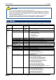
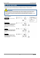
5-4. Modes
Details on each mode are provided as follows. (* Operations are slightly different depending on the model.)
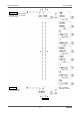
Mode Item LCD display Details
Detection
Mode
- Gas
concentration
Gas name
Normal state
Gas Alarm
Test Mode
- Gas
concentration
Perform the alarm test.
Zero Adjustment (Span
Adjustment)
1-1 ZERO
(1-1 SPAN)
Perform the zero adjustment.
(In case of oxygen 0 - 25 %, perform the span adjustment.)
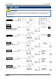
Setting Display 1-2.CONFIRM Show the setting of the typical menu.
• First alarm setpoint (AL1)
• Second alarm setpoint (AL2)
• Alarm delay time
• Zero suppression value
• Zero follower ON/OFF
• Indicator type
Peak Value Display 1-3 PEAK Display the peak concentration value when a gas is detected.
Main Unit Version Display 1-4 RM VER Show the program version of the main unit.
AMP Version Display 1-5 AMP VER Show the program version of the amplifier unit.
RS-485 Address Display 1-6 ADDRESS Show the address.
RS-485 Communication
Setting Display
1-7 485 PTRN Show the setting status of the communication function.
Maintenance
Mode
(User)
Regular Maintenance Mode
Switching
1-8 M MODE Switch to the regular maintenance mode.
Gas Introduction Display 2-0 GAS TEST Perform the gas introduction test in the regular maintenance mode.
Zero Adjustment 2-1 ZERO Perform the zero adjustment.
Span Adjustment 2-2 SPAN Perform the span adjustment.
Last Calibrated Date 2-3 LAST CAL Show the last calibrated date.
Heater Current Display 2-4 CUR CAL Show the heater current.
Environmental Setting 1 2-5 SETTING1 Operation setting
SE 0 INHIBIT setting (INHIBIT)
SE 1 Alarm setpoint value setting (ALM P)
SE 2 Alarm delay time setting (ALM DLY)
SE 3 Fault test (F TEST)
Environmental Setting 2 2-6 SETTING2 Functions setting
SE 0 Address setting (ADDRESS)
SE 1 Date/Time setting (DAY TIME)
SE 2 Zero suppression value setting (SUPPRESS)
SE 3 Zero suppression type setting (SUP TYPE)
SE 4 Contact setting for alarm test (TEST RLY)
SE 5 External output setting for alarm test (TEST4-20)
SE 6 Energized/De-energized setting (RLY PTRN)
SE 7 Alarm type setting (ALM TYP)
SE 8 Alarm pattern setting (ALM PTRN)
SE 9 Alarm value limiter setting (AL LIMIT)
SE10 Fault alarm pattern setting (FLT PTRN)
SE11 Zero follower ON/OFF setting (ZERO F)
SE12 External output in maintenance mode setting (MNT OUT)
SE13 External output adjustment (MA 4-20)
Maintenance
Mode
(Regular
maintenance)
Environmental Setting 3 2-7 SETTING3 Adjustment and setting
SE 0 Amplifier initialization (AMP DEF)
SE 1 Heater current adjustment (HEAT ADJ)
SE 2 Load voltage adjustment (LOAD ADJ)
SE 3 Measured gas selection (GAS SEL)
SE 4 Peak hold setting (PEAKHOLD)
SE 5 First alarm LCD setting (ALM1 LCD)
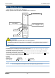
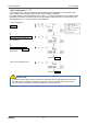
CAUTION
• Do not turn off the indicator/alarm unit during the initial clear.
• If a new sensor is installed or the sensor is replaced after the indicator/alarm unit is started, the
sensor must be warmed up for a specified period which is determined depending on the type of
the sensor. After the warm-up is completed, perform a gas calibration. Read also the operating
manual of the gas detector head.
• During the warm-up, the alarm activation and output signals are unstable. Provide a prior
notification to the related sections so that they can prepare for false abnormalities.