PT1E-1050 Indicator/Alarm Unit RM-5000 Series Operating Manual Request for the Customers • • • • • Read and understand this operating manual before using the indicator/alarm unit. Use the indicator/alarm unit in accordance with the operating manual. Regardless of warranty period, we shall not make any indemnification for accidents and damage caused by using this product. Make sure to read the warranty policy specified on the warranty.
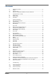
RM-5000 1 1-1. 1-2. 1-3. Outline of the Product.............................................................................................. 3 Preface .................................................................................................................... 3 Purpose of use ........................................................................................................ 3 Definition of DANGER, WARNING, CAUTION, and NOTE ..................................... 4 2 2-1. 2-2.
1 Outline of the Product 1-1. Preface 1 Outline of the Product 1-1. Preface Thank you for choosing our indicator/alarm unit RM-5000 series for use with the gas detection and alarm system. Please check that the model number of the product you purchased is included in the specifications on this manual. This manual explains how to use the indicator/alarm unit and its specifications. It contains information required for using the indicator/alarm unit properly.
1 Outline of the Product 1-3. Definition of DANGER, WARNING, CAUTION, and NOTE • The gas detection and alarm system is a safety unit, not an analyzer or densitometer which performs quantitative/qualitative analysis/measurement for gases. You must understand the features of the indicator/alarm unit before using it, so that you can use it properly.
2 Important Notices on Safety 2-1. Danger cases 2 Important Notices on Safety 2-1. Danger cases DANGER This is not an explosion-proof unit.
2 Important Notices on Safety 2-2. Warning cases 2-2. Warning cases WARNING Specified devices Connect the indicator/alarm unit only to the specified devices. If it is connected to any unspecified device, the indicator/alarm unit or the connected device may be damaged. Power supply Before turning on the indicator/alarm unit, always check that the voltage is properly applied. Do not use an unstable power supply because it may cause malfunctions.
2 Important Notices on Safety 2-3. Precautions 2-3. Precautions CAUTION Do not use a transceiver near the indicator/alarm unit. Radio wave from a transceiver, etc. near the indicator/alarm unit or its cables may disturb indication reading. If a transceiver or other radio wave transmitting device is used, it must be used in a place where it disturbs nothing. To restart the indicator/alarm unit, wait for five seconds or more before doing it.
3 Product Components 3-1. Main unit and accessories 3 Product Components 3-1.
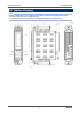
3 Product Components 3-2. Outline drawing 3-2. Outline drawing NOTE Install the indicator/alarm unit in a single-unit case (option) or multi-unit case (option) before using it. This section explains the unit in a single-unit case. For information on using a multi-unit case, see the operating manual of the multi-unit case.
3 Product Components 3-3. Names and functions for each part 3-3.
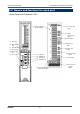
3 Product Components Number in the figure (1) 3-3. Names and functions for each part Item Function POWER switch Power switch. (2) MODE key (3) ALM2/▲ key (4) ALM1/▼ key (5) TEST/SET key (6) Power lamp (POWER) Used to enter the maintenance mode. It is also used to cancel or skip in a specific mode. Used to switch screen or change a value (UP). Also used to display the second alarm (ALM2) setpoint. Used to switch screen or change a value (DOWN).
3 Product Components 3-3.
3 Product Components 3-3. Names and functions for each part Attach or detach the indicator/alarm unit from the single-unit case or multi-unit case according to the following procedure. (1) Attaching procedure • Open the front cover of the indicator/alarm unit. • Make sure that the power switch of the indicator/alarm unit is OFF. • Insert the indicator/alarm unit along the rail into the single-unit case or multi-unit case.
3 Product Components 3-3. Block diagram 3-3. Block diagram Detector head (option) Amplifier (*1) Controller (CPU) Power supply part POWER INPUT (24 VDC) Alarm contact controller Gas alarm contact (ALM1, ALM2) Fault alarm contact (FAULT) * Standard setting of contact activation • De-energized (De-energized at a normal state) • ON-ALARM (Closed contact at an alarm state) Controller (CPU) LCD display Bar meter, gas name display, concentration display, unit display, etc.
4 How to Use 4-1. Before using the indicator/alarm unit 4 How to Use 4-1. Before using the indicator/alarm unit Not only the first-time users but also the users who have already used the product must follow the operating precautions. Ignoring the precautions may damage the indicator/alarm unit, resulting in inaccurate gas detection. NOTE Install the indicator/alarm unit in a single-unit case (option) or multi-unit case (option) before using it. This section explains using the single-unit case.
4 How to Use 4-3. Precautions for system designing Do not install the indicator/alarm unit in a place exposed to direct sunlight or sudden changes in the temperature. When you select installation sites, avoid a place where it is exposed to direct sunlight or radiant heat (infrared rays emitted from a high-temperature object), and where the temperature changes suddenly.
4 How to Use 4-3. Precautions for system designing Lightning cannot be prevented. Cables installed in a metal conduit or under the ground cannot be completely protected from inductive lightning surge caused by lightning. Although complete elimination of disasters caused by lightning is impossible, the following protective measures can be taken. Take appropriate measures in accordance with the importance of the facilities and the environment. • Connect the transmission signal route by using optical fiber.
4 How to Use 4-3. Precautions for system designing If load is to be activated, appropriate measures must be taken to stabilize the operation of the indicator/alarm unit and protect the alarm contact referring to the following information. • Relay it with an external relay at a lower voltage of 100 VAC or below (contact amplification). At the same time, the surge absorbing part SK1 suitable for the specifications must be attached to the external relay.
4 How to Use 4-4. How to install 4-4. How to install NOTE Install the indicator/alarm unit in a single-unit case (option) or multi-unit case (option) before using it. This section explains using the single-unit case. For information on using the multi-unit case, see the operating manual of the multi-unit case.
4 How to Use 4-4. How to install When installed in one row vertically and N columns horizontally Multi-point panel cutout dimensions Panel thickness N: Buzzer unit + Indicator/alarm unit After drilling holes in the panel to install a single-unit case, attach the indicator/alarm unit according to the following procedure. (1) Insert the single-unit case from the rear terminal plate side to the panel front side.
4 How to Use 4-5. How to wire 4-5. How to wire CAUTION • Use the specified cables for each of the connections between the indicator/alarm unit and the detector head. • When wiring, be careful not to apply stresses on the terminal plate when (overweight) cables are installed. • The power cables and signal cables must not be installed together with the motor power cables, etc. • When stranded wires are used, prevent wires from contacting each other. • Use the specified tools to wire.
4 How to Use 4-5. How to wire NOTE Install the indicator/alarm unit in a single-unit case (option) or multi-unit case (option) before using it. This section explains using the single-unit case. For information on using the multi-unit case, see the operating manual of the multi-unit case.
4 How to Use 4-5.
4 How to Use 4-5. How to wire Connection conditions • Cable: 0.08 - 2.5 mm2 • Bare wire length: 8 - 9 mm • Connecting tools: Dedicated screwdrivers manufactured by WAGO and equivalent (edge width 3.5 x 0.5 mm or less) • When using a general-purpose screwdriver, use one with an edge width from 2.5 mm to 3.5 mm. Do not use a screwdriver that does not fit into the screwdriver slot or cannot open the spring properly. z Dedicated products 210-120J: ..... Standard model 210-350/01:.. Short model 210-258J: ...
4 How to Use 4-5. How to wire When cables are connected to the terminal plate, use the dedicated screwdriver or a compatible flathead screwdriver to do so as shown below. CAUTION The right tools must be used. Only one wire can be connected to one wiring hole. When the wire is inserted into the driver slot by mistake, it does not contact the conductive part. This may cause defective electric conduction or heating.
4 How to Use 4-5. How to wire Connect the indicator/alarm unit to your grounding terminal. WARNING Before turning on the indicator/alarm unit, never fail to connect it to a grounding terminal. For stable operation of the indicator/alarm unit and safety, it must be connected to a grounding terminal. Do not connect the grounding wire to a gas pipe. The grounding must be made as D type grounding (below 100 Ω of grounding resistance).
4 How to Use 4-5.
4 How to Use 4-5. How to wire OX-5001, OX-5002 Gas detector head + - OX-5001 11 12 13 14 Detector head signal OX-5001: Sensor direct signal OX-5002: Current signal (4 - 20 mA DC) NOTE To construct an intrinsically safe explosion-proof system by connecting the indicator/alarm unit to a gas detector head with an intrinsically safe explosion-proof structure, connect the dedicated Zener Barrier between them. Read also the operating manual of the gas detector head.
4 How to Use 4-5. How to wire EC-5002 Gas detector head + - AC AC EC-5002 11 Power supply for pump 100 VAC 12 13 14 NOTE To construct an intrinsically safe explosion-proof system by connecting the indicator/alarm unit to a gas detector head with an intrinsically safe explosion-proof structure, connect the dedicated Zener Barrier between them. Read also the operating manual of the gas detector head.
4 How to Use 4-5.
5 How to Operate 5-1. Preparation for start-up 5 How to Operate 5-1. Preparation for start-up Before connecting a power supply, read and understand the following precautions. Ignoring these precautions may cause an electric shock or damage the indicator/alarm unit. • Check that the wiring is connected to external device properly. • Check that the power supply voltage is compliant with the specifications.
5 How to Operate 5-2. Basic operating procedures 5-2. Basic operating procedures Normally, the detection mode is used for normal operations. (The detection mode is activated after the power is turned on.) Lamp on Lamp off Lamp blinking <> The indicator/alarm unit is restarted after recovering from fault.
5 How to Operate 5-3. How to start the indicator/alarm unit 5-3. How to start the indicator/alarm unit • • • • Before turning on the power switch, check whether the indicator/alarm unit is installed properly. Open the front cover of the indicator/alarm unit to find the power switch. Turn ON the power switch. After the indicator/alarm unit completes the start-up, it enters the detection mode swiftly.
5 How to Operate 5-4. Modes CAUTION • Do not turn off the indicator/alarm unit during the initial clear. • If a new sensor is installed or the sensor is replaced after the indicator/alarm unit is started, the sensor must be warmed up for a specified period which is determined depending on the type of the sensor. After the warm-up is completed, perform a gas calibration. Read also the operating manual of the gas detector head. • During the warm-up, the alarm activation and output signals are unstable.
5 How to Operate Fault Detailed View HART Device Synchronization Setting HART Device Setting Return to the user mode Factory Mode Switching 5-4.
5 How to Operate 5-5. Detection mode 5-5. Detection mode Display a gas name, full scale value, etc. that have been set in advance. Full scale value Gas concentration bar meter display Gas concentration digital display Gas name Power lamp CAUTION A reading under zero is suppressed with the 10% FS suppression. A reading that is 10% FS or more under zero is displayed as "-0.0", which prevents an accurate gas detection and needs the zero adjustment.
5 How to Operate 5-6. Alarm test mode 5-6. Alarm test mode This is used when dummy signals the same as the signals of the gas concentration are generated to check the alarm lamp activation of the indicator/alarm unit and the transmission to external circuits. WARNING Before starting the alarm test (transmission test), provide a notification to the related sections so that they can prepare for false abnormalities (external output signals and alarm contact).
5 How to Operate 5-7. User mode 5-7. User mode WARNING After the adjustment is completed, never fail to press the MODE key to return to the detection mode. (If the indicator/alarm unit remains in the user mode, it automatically returns to the detection mode in ten hours.) <> Lamp on Lamp off Lamp blinking Detection Mode Press the MODE key for three seconds. During maintenance During inhibit User Mode Zero Adjustment => P40 1-1. ZERO Perform the zero adjustment.
5 How to Operate 5-7. User mode 1-7. 485 PTRN Show the communication setting of RS-485. (Only on a model with an option mounted) See "7-2. Regular maintenance mode". 1-8. M MODE Switch to the regular maintenance mode. To 1-1.
5 How to Operate 5-7. User mode This is used to perform the zero adjustment. Before starting the zero adjustment, let the detector head (sensor) draw the zero adjustment gas and wait until the reading is stabilized. For oxygen deficiency alarm specification (O2:0 - 25%), "1-1" is the span adjustment. In this case, the AIR adjustment is performed, so that fresh air must be introduced to adjust it to 20.9%. For information on the span adjustment, see “7-3.
5 How to Operate 5-7. User mode This is used to check the setting of typical menus. <> Lamp on Lamp off Lamp blinking 1-2. CONFIRM Press SET key.
5 How to Operate 5-8. How to exit 5-8. How to exit To turn off the indicator/alarm unit, open the front cover of the main unit, and turn "OFF" the power switch. Then, turn off the power supply (24 VDC) to the indicator/alarm unit. WARNING • When the indicator/alarm unit is turned off, an alarm may be activated on the upper (central) system. Before turning off the indicator/alarm unit, the inhibit (point skip) on the upper (central) system must be activated.
6 Operations and Functions 6-1. Gas alarm activation 6 Operations and Functions 6-1. Gas alarm activation Gas alarm: Triggered when the concentration of detected gas reaches or exceeds the alarm setpoint value. <> NOTE The alarm setpoint (first alarm and second alarm) is factory-set. Although the alarm delay time (standard: 2 seconds) works in the indicator/alarm unit to prevent a false activation, it can be cancelled if not needed.
6 Operations and Functions 6-1. Gas alarm activation Alarm Indicator Lamp (ALM1: Red), (ALM2: Red) The alarm consists of two steps. Each of them is triggered when the respective alarm setpoint value is reached to or exceeded. The alarm indicator lamp goes out when the gas concentration settles below the alarm setpoint after a reset operation. First alarm Second alarm The alarm contact consists of two steps.
6 Operations and Functions 6-1. Gas alarm activation "Alarm Pattern Example (H-HH)" Normal Gas concentration Alarm Recovered SP. HH side (second) SP.
6 Operations and Functions 6-1. Gas alarm activation "Alarm Pattern Example (L-LL)" Normal Gas concentration Alarm Recovered SP. L side (first) SP.
6 Operations and Functions 6-2. Fault alarm activation In case of responding to a leaked gas When a gas alarm is triggered, take actions in accordance with your management rules of gas alarm. Normally, take the following actions. • Check the reading of the indicator/alarm unit. NOTE If a gas leak is momentary, the reading may already have dropped when you check it.
6 Operations and Functions 6-3. External output operation 6-3. External output operation Specifications Signal Transmission System 4 - 20 mA Electric current transmission (non-isolated) Transmission Path Transmission Distance CVVS Below 1 km Connection Load Resistance (1) Detection Mode (No Alarm) (2) Detection Mode (Gas Alarm) (3) Initial Clear Below 300 Ω 4 - 20 mA (concentration output) 4 - 20 mA (concentration output) Depending on the setting of (4) 2.5 mA setting: 2.
6 Operations and Functions 6-3. External output operation External output 22 mA 20 mA Detection mode 16 mA Maintenance mode 4 mA 2.5 mA High range Low range Zero suppression Full scale 0 Gas concentration NOTE NC-5001W offers two reading ranges (low and high ranges). If the displayed combustible gas concentration rises above the full scale of the low range, the display is automatically switched to the high range.
6 Operations and Functions 6-4. Other functions 6-4. Other functions Some types of detector heads connected to the indicator/alarm unit are influenced by environmental changes (temperature, humidity, and other characteristics) or interference gases (interference characteristics) in no small measure, which affects the reading. Therefore, the reading might fluctuate around zero even in a normal state with no gas leakage.
6 Operations and Functions 6-4. Other functions The maximum (or minimum) concentration value after an alarm is triggered is displayed using the bar meter blinking and a numeric value even after the reading returns to a normal status. The numeric value is displayed in 1-3.PEAK in the maintenance mode (user). To disable the peak display, keep the SET key pressed in 1-3.PEAK in the maintenance mode (user).
7 Maintenance 7-1. Maintenance intervals and items 7 Maintenance The indicator/alarm unit is an important instrument for the purpose of safety. To maintain the performance of the indicator/alarm unit and improve the reliability of safety, perform a regular maintenance. NOTE To use the multi-unit case, also refer to the separate operating manual. 7-1. Maintenance intervals and items • Daily maintenance: Perform maintenance before beginning to work.
7 Maintenance 7-1. Maintenance intervals and items • We provide services on regular maintenance including span adjustment, other adjustments and maintenance. To make the calibration gas, dedicated tools, such as a gas cylinder of the specified concentration and gas sampling bag must be used. Our qualified service engineers have expertise and knowledge on the dedicated tools used for services, along with other products.
7 Maintenance 7-2. Regular maintenance mode 7-2. Regular maintenance mode WARNING After the adjustment is completed, never fail to press the MODE key to return to the detection mode. (If the indicator/alarm unit remains in the maintenance mode, it automatically returns to the detection mode in ten hours.
7 Maintenance 7-2. Regular maintenance mode <> Lamp on Lamp off Lamp blinking User Mode In "1-8.M MODE", press the SET key. During maintenance During inhibit Then press the SET key again for three seconds. Regular Maintenance Mode 2-0. GAS TEST Perform a test with the gas. Similar to the detection mode, the reading changes and the alarm lamp lights up after the gas is introduced, but the contact is not activated. (Alternate Display) 2-1. ZERO Perform the zero adjustment.
7 Maintenance 7-2. Regular maintenance mode 2-6. SETTING2 Specify the environmental setting 2. Environmental Setting 2 => P59 2-7. SETTING3 Specify the environmental setting 3. Environmental Setting 3 => P64 2-8. FAULT This is used (by the manufacturer) to investigate and analyze the causes of faults. This is not used by the user. 2-9. HART SET Used for synchronization setting of HART devices.(Only on a model with an option mounted) 2-10. HART SET Used for setting of HART devices.
7 Maintenance 7-2. Regular maintenance mode In the environmental setting 1, specify the operation setting. <> Lamp on Lamp off Lamp blinking 2-5. SETTING1 Press SET key. During maintenance During inhibit SE 0. INHIBIT Set Inhibit. Press the ▲ or ▼ key to select either ON/OFF, and then press the SET key to confirm the selection. When ON is selected, the character I is displayed on the LCD.
7 Maintenance 7-2. Regular maintenance mode <> Lamp on Lamp off Lamp blinking SE 1. ALM P Press SET key. During maintenance During inhibit First Alarm Setpoint Value Setting Press the ▲ or ▼ key to change the value, and then press the SET key to confirm the value. Second Alarm Setpoint Value Setting Press the ▲ or ▼ key to change the value, and then press the SET key to confirm the value. Return to SET 1.
7 Maintenance 7-2. Regular maintenance mode In the environmental setting 2, specify the settings of functions. (* It is recommended that setting changes should be recorded in a log.) The environmental setting 2 includes setting menus which are usually not used. Be careful not to change these settings by mistake. <> Lamp on Lamp off Lamp blinking 2-6. SETTING2 Press SET key. During maintenance During inhibit SE 0.
7 Maintenance 7-2. Regular maintenance mode Press the ▲ or ▼ key to select either ON/OFF, and then press the SET key to confirm the selection. When ON is selected, the test concentration is output as the external output during an alarm test. When OFF is selected, the output is kept at the one before the alarm test mode is entered. Energized/De-energized Contact Setting => P63 SE 6. RLY PTRN Select either energized/de-energized for the contact. SE 7. ALM TYPE Set the alarm type.
7 Maintenance 7-2. Regular maintenance mode SE 12. MNT OUT Set the external output for the maintenance mode. Press the ▲ or ▼ key to select either 2.5 mA/4.0 mA /HOLD (previous value)/4 - 20 mA (linked to display value), and then press the SET key to confirm the selection. SET 13. MA 4-20 Adjust the external output (4 20 mA). After selecting 4 mA or 20 mA, press the SET key to enable adjustment. After adjustment of 4 mA is completed, perform the adjustment of 20 mA.
7 Maintenance 7-2. Regular maintenance mode <> Lamp on Lamp off Lamp blinking SE 1. DAY TIME Press SET key. During maintenance During inhibit Date/Time Setting Display Press SET key. Year Setting Press the ▲ or ▼ key to change the value, and then press the SET key to confirm the value. Month Setting Press the ▲ or ▼ key to change the value, and then press the SET key to confirm the value.
7 Maintenance 7-2. Regular maintenance mode <> Lamp on Lamp off Lamp blinking SE 6. RLY PTRN Press SET key. During maintenance During inhibit First Alarm Contact Setting Press the ▲ or ▼ key to select either nd (de-energized) or nE(energized), and then press the SET key to confirm the selection.
7 Maintenance 7-2. Regular maintenance mode In the environmental setting 2, specify the settings of functions. (* It is recommended that setting changes should be recorded in a log.) The environmental setting 2 includes setting menus which are usually not used. Be careful not to change these settings by mistake. <> Lamp on Lamp off Lamp blinking 2-7. SETTING3 Press SET key. During maintenance During inhibit SE 0.
7 Maintenance 7-2. Regular maintenance mode Setting of the gas name of measured gas and the full scale. => P71 SE 3. GAS SEL Select and set the gas name of measured gas and the full scale. Press the ▲ or ▼ key to make a selection, and then press the SET key to confirm the selection. SE 4. PEAKHOLD Select either ON/OFF of holding the maximum concentration value when a gas is detected. Press the ▲ or ▼ key to select either ON/OFF, and then press the SET key to confirm the selection. SE 5.
7 Maintenance 7-2. Regular maintenance mode SE 7. DR OUT Set the double range external output. SE 8. FLOW SET Select either ON or OFF of the low flow rate alarm activation. SE 9. OUT SET Set the resolution of external output. Press the ▲ or ▼ key to select either the same number of divisions as the display (standard setting) or 1000 divisions, and then press the SET key to confirm the selection. SE 10. 485 PTRN Set the RS-485 communications.
7 Maintenance 7-2. Regular maintenance mode SE 11. GRN ADJ Adjust the brightness of the LCD backlight (green LED). Press the ▲ or ▼ key to increase or decrease the value to adjust the brightness, and then press the SET key to confirm the value. SE 12. RED ADJ Adjust the brightness of the LCD backlight (red LED). Press the ▲ or ▼ key to increase or decrease the value to adjust the brightness, and then press the SET key to confirm the value. SE 13.
7 Maintenance 7-2. Regular maintenance mode To SE 0.
7 Maintenance 7-3. Gas calibration method 7-3. Gas calibration method Perform a gas calibration on the detector head (sensor) connected to the indicator/alarm unit in each mode (zero adjustment mode and span adjustment mode) using the calibration gas. • Zero adjustment gas (collected in a gas sampling bag) • Span gas (collected in a gas sampling bag) • Gas sampling bags WARNING After the adjustment is completed, never fail to press the MODE key to return to the detection mode.
7 Maintenance 7-3. Gas calibration method This is used to perform the span adjustment on the detector head (sensor). For the oxygen deficiency alarm specification (O2: 0 - 25 vol%), this is the same as “1-1”. <> Lamp on Lamp off Lamp blinking 2-2. SPAN Press SET key. During maintenance During inhibit Gas Introduction Introduce a gas to the connected detector head (sensor), and then press the SET key when the reading is stabilized.
7 Maintenance 7-3. Gas calibration method <> Lamp on Lamp off Lamp blinking SET 3. GAS SELECT Press SET key. During maintenance During inhibit Press the ▲ or ▼ key to select the target model "GP", "nc", or "nc d", and then press the SET key to confirm the value.
7 Maintenance 7-4. How to clean 7-4. How to clean Clean the indicator/alarm unit if it becomes extremely dirty. The indicator/alarm unit must be turned off while cleaning it. Use a waste cloth to remove dust. Do not use water or organic solvent for cleaning because they may cause malfunctions. 7-5. How to replace the fuse Make sure that the power switch of the indicator/alarm unit is OFF. Pull out the fuse from the fuse holder (see the figure on the right). Insert a new fuse in the fuse holder.
8 Storage, Relocation and Disposal 8-1. Procedures to store the indicator/alarm unit or leave it for a long time 8 Storage, Relocation and Disposal 8-1. Procedures to store the indicator/alarm unit or leave it for a long time The indicator/alarm unit must be stored under the following environmental conditions. • In a dark place under the normal temperature and humidity away from direct sunlight • In a place where gases, solvents or vapors are not present • In a place free from vibrations or shocks 8-2.
9 Troubleshooting 8-3. Disposal of products 9 Troubleshooting The troubleshooting does not explain the causes of all the malfunctions which occur on the indicator/alarm unit. This simply helps to find the causes of malfunctions which frequently occur. If the indicator/alarm unit shows a symptom which is not explained in this manual, or still has malfunctions even though remedial actions are taken, please contact RIKEN KEIKI.
9 Troubleshooting 8-3. Disposal of products Symptom/Display The power cannot be turned on.
9 Troubleshooting 8-3. Disposal of products Symptoms The reading rises (drops) and it remains so. A gas alarm is triggered despite of no gas leak and no other abnormalities at the detection point. Slow response Span adjustment impossible RM-5000 Causes Actions Drifting of sensor output Perform the zero adjustment (fresh air adjustment). Presence of interference gas Disturbances by interference gases, such as solvents, cannot be eliminated completely.
10 Product Specifications 10-1. List of specifications 10 Product Specifications 10-1.
10 Product Specifications 10-1.
10 Product Specifications Model Gas to be detected Applicable gas detector head Gas alarm type Detector head signal Cable for gas detector head Distance to gas detector head Functions Power consumption Model Gas to be detected Applicable gas detector head Gas alarm type Detector head signal Cable for gas detector head Distance to gas detector head Functions Power consumption 10-2.
11 Definition of Terms 11 Definition of Terms %LEL vol% A percentage unit of the concentration of a combustible gas assuming the lower explosive limit (LEL) of the combustible gas as 100. LEL (Lower Explosion Limit) refers to the lowest concentration of a combustible gas in air capable of causing explosion when ignited.
Warranty Policy RIKEN KEIKI CO., LTD., warrants gas alarm equipment sold by us to be free from defects in materials, workmanship, and performance for a period of one year from date of shipment from RIKEN KEIKI CO., LTD., Inc. Any parts found defective within that period will be repaired or replaced, at our option, free of charge.