Pioneer-R16 Gas Monitor Operator’s Manual Edition 7/2/97 RKI INSTRUMENTS, INC RKI Instruments, Inc.
Chapter 1: Description About the Pioneer-R16 Gas Monitor The Pioneer-16R is a 19” rack mounting, fixed continuous-monitoring instrument. This multiple channel gas monitor is capable of detecting gas at up to sixteen locations. Four display screens on the front panel simultaneously display the gas readings of all active channels. The Pioneer-16R includes audible and visual alarms that warn you of hazardous gas conditions. The alarm circuit includes three levels of alarm: alarm 1, alarm 2, and alarm 3.
• • • condition such as an open sensor connection or a circuit board fault. ALARM 1 Light The ALARM 1 light is to the right of the FAIL light. It turns on when the monitor is experiencing an alarm 1 condition. ALARM 2 Light The ALARM 2 light is to the right of the ALARM 1 light. It turns on when the monitor is experiencing an alarm 2 condition (the ALARM 1 light is also on). ALARM 3 Light The ALARM 3 light is to the right of the ALARM 2 light.
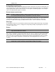
power I/O card includes external wiring terminal strips, four relays, and two fuses. Terminal Strips • • • • AC Terminal Strip The 3-point AC terminal strip is on the right side of the card. You connect the incoming AC power source to the AC terminal strip. The AC terminal strip is labeled TB2 on the circuit board. Common Alarm Relay Terminal Strip The 12-point common alarm relay terminal strip is located to the left of the AC terminal strip.
analyzer card. Analog Output terminal strip The 2-point analog output terminal strip (terminals 8 and 9) is directly above the detector terminal strip. You connect wiring from a recording device (if applicable) to the analog output terminal strip. The output at the analog output terminal strip is 4 to 20 mA or 0 to 1 V. The output is selectable by jumpers on the analyzer card. The standard (default) output is 4 to 20 mA.
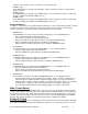
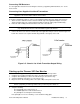
Chapter 2: Installation and Startup Mounting the Pioneer-16R Gas Monitor The subrack which houses the monitor is suitable for mounting in a 19” rack or rack enclosure. Position the subrack in the rack as desired and use the mounting flange on each side of the subrack to mount it to the rack with screws. .28” diameter slotted holes are provided on the flanges for mounting. Two .20” diameter holes are also provided on the mounting flanges for mounting of a handles if desired. Ø .20, 4X Ø .28, 4X 18.94 18.
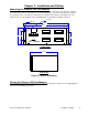
Connecting External Alarms Perform the following procedure to connect external alarms to the Pioneer. N O T E : The analyzer card includes external alarm connections that are dedicated to the applicable channel only. 1. Guide the wiring of the external alarm to the rear of the subrack. CAUTION: If the external alarm device is powered by AC current, do not route the external alarm wiring and detector wiring through the same conduit hub or cable.
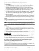
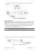
2. Connect the leads from the external alarm to the terminals on the appropriate external wiring terminal strip. NO COM NC Figure 2-3: External Alarm Wiring Connecting Recorders Perform the following procedure to connect a recording device to the Pioneer. The output at the analyzer card’s analog output terminal strip is a 4 to 20 mA or 0 to 1 V signal that is proportional to the detection range of the applicable detector. Unless specified, the analyzer card is set up at the factory for 4 to 20 mA output.
Connecting RKI Detectors See the applicable detection insert for wiring the detector(s) supplied by RKI Instruments, Inc. To the Pioneer-R16. Connecting User-Supplied 4 to 20 mA Transmitters N O T E :See Generic 4 - 20 mA Transmitter Insert for more detailed information related to the use of usersupplied 4 to 20 mA transmitters with the Pioneer-R16. Perform the following procedure to connect a 4 to 20 mA transmitter (that you supply) to the Pioneer: 1.
6. Perform the start-up procedure for each detector as described in the gas detection insert(s).
Chapter 3: Operation Normal Operation Normal operation is defined as follows: • The start-up procedure is complete. • The Pioneer is not indicating an alarm 1, alarm 2, alarm 3, or fail condition. • The Pioneer is not running the Instrument Setup, Channel Setup, Calibrate, or Display Setpoints and Readings program. During normal operation, the Pioneer simultaneously displays the target gas, unit of measure, and current gas reading for all active channels.
relay is factory-set for normally energized and is not user-selectable. Alarm 1 Condition This section describes the audible and visual indications for an alarm 1 condition and suggests response to an alarm 1 condition. • Alarm 1 condition indications When the gas reading of an active channel reaches the alarm 1 setpoint, the Pioneer senses an alarm 1 condition.
When the gas reading of an active channel reaches the alarm 3 setpoint, the Pioneer senses an alarm 3 condition.
• • • • • • • • • • • Alarm Off Delay Relay Action Alarm Logic Alarm Silence Alarm Hysteresis Calibration Time Out Instrument ID (RS-232 or RS-485 address) Noise Filter Maximum Number of Channels (for use when connecting to other Pioneers) Zero Suppression Instrument Label Navigating Through the Instrument Setup Program Use the program buttons on the front panel to enter the program, move forward or backward through the program, change settings within the program, and save or cancel changes to the program
2. Press the ENTER button to continue the program. The program displays the Alarm OFF Delay screen. • Alarm Off Delay Screen This screen indicates the length of time that the Pioneer-R16 delays turning off alarm indications (buzzer and relays) after an alarm 1, alarm 2, or alarm 3 condition passes. You can choose from a range of 0 Seconds to 60 Minutes. The default setting is 0 Minutes, 0 Seconds. - • To accept the alarm off delay setting and continue the program, press the ENTER button.
- • Alarm Silence Screen This screen indicates how the buzzer operates during alarm conditions. If the setting is ON, you can use the reset switch to silence the buzzer during alarm conditions. If the setting is O F F, you cannot silence the buzzer until all alarm conditions pass. The default setting is ON. - • To accept the alarm logic setting and continue the program, press the ENTER button. The program displays the Alarm Silence screen. To update the alarm logic setting: 1.
The second time-out feature affects the Fresh Air and Calibration screens only. These are the screens you use during calibration to adjust the zero and span readings (either at the transmitter or the Pioneer). The Pioneer automatically returns to the normal screen if you do not move from the Fresh Air or Calibration screen within the time-out setting specified in the screen below. You can choose from a range of 10 to 100 minutes (in increments of 10). The default setting is 10 Minutes.
- • To accept the noise filter setting and continue the program, press the ENTER button. The program displays the Number of Channels screen. To update the noise filter setting: 1. Use the UP/YES or DOWN/NO button to display the setting you want. 2. Press the ENTER button to continue the program. The program displays the Number of Channels screen. Number of channels screen This screen indicates the maximum number of channels possible for the Pioneer-R16.
- • To accept the instrument label setting and continue the program, press the ENTER button until the Instrument Setup Exit screen displays. To update the instrument label setting: 1. Use the ENTER button to select the character you want to change. (The character flashes when it is selected.) 2. Press the UP/YES or DOWN/NO button to display the character you want, then press the ENTER button to select the next character. 3.
instrument, display, and channel software programs. 1. Press and hold down the reset switch to enter the program. 2. When the DISPLAY VERSIONS screen appears, release the reset switch. 3. Press and release the reset switch to display the remaining software versions and return to the normal screen. • To display TWA and STEL readings: The Pioneer continuously computes Time Weighted Average (TWA) and Short Term Exposure Limit (STEL) readings for all active channels.
1. Press and hold down the reset switch to enter the program. 2. When the SELF CHECK screen appears on the display screen, release the reset switch. The Pioneer performs the self check procedure and returns to the normal screen. This process takes approximately 5 seconds. • To reset Minimum/Maximum readings: If you reset the minimum and maximum readings, you cannot retrieve the minimum and maximum readings previously stored by the Pioneer. 1. Press and hold down the reset switch to enter the program. 2.
Chapter 4: Maintenance Preventive Maintenance Preventive maintenance of the Pioneer-R16 consists of daily, monthly, and quarterly procedures to ensure that the detectors remain on zero (20.9 for oxygen) in fresh air and are responsive to gas. The gas detection inserts includes preventive maintenance schedules for the detectors supplied with your Pioneer-R16. Troubleshooting The troubleshooting guide describes symptoms, probable causes, and recommended action for problems you may encounter with the Pioneer.
• Probable causes - The Pioneer is experiencing false readings due to Radio Frequency Interference (RFI) or Electromagnetic Interference (EMI). - The noise filter setting is too low. - The zero suppression setting is too low. • Recommended action 1. Verify that the detector wiring is properly shielded (see the Installation section(s) in the applicable detection insert). 2. Verify that the detector wiring is correct and secure. 3.
5. Install the appropriate replacement fuse in the fuse holder. 6. Align the Power I/O card in its card guide with the fuses on the right and the terminal blocks on the top side of the card. 7. Gently push the Power I/O card into its socket on the main circuit board. 8. Plug in or turn on all incoming power to the monitor at the power source end. Replacing the DC Fuse 1. Turn off or unplug all incoming power to the monitor at the power source end. 2. Gain access to the rear of the monitor. 3.