
Operator`s manual


M2 Transmitter Operator’s Manual 56
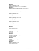
Register 3
Register 3 is the supply voltage (0.1 volt per count).
Registers 4 - 11
The 16 bytes in these registers contain the same ASCII text information that is displayed
on the M2’s LCD (not NULL Terminated).
Register 12
Register 12 is the range (full scale readout).
Register 13
Register 13 is the alarm 1 set point.
The decimal point location is the same as specified in Register 1.
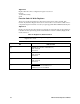
[9] Calibration Activity Flag
0=No Calibration Activity
1=Calibration Activity Has Occurred
[8] Fail Status
0 = Fail Not Asserted
1 = Fail Asserted
[7:6] Alarm 2 Status
0 = No Alarm
1 = Unacknowledged Alarm
2 = Acknowledged Alarm
3 = Unused Code
[5:4] Alarm 1 Status
0 = No Alarm
1 = Unacknowledged Alarm
2 = Acknowledged Alarm
3 = Unused Code
[3] Overscale Status
0 = Not Overscale
1 = Overscale
[2] Fail Relay Status
0 = Not Energized
1 = Energized
[1] Alarm 2 Relay Status
0 = Not Energized
1 = Energized
[0] Alarm 1 Relay Status
0 = Not Energized
1 = Energized
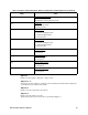
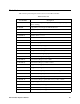
Table 13: Register 2, Operating State, Alarms & Relays Bit & Field Assignments (Continued)
Bit(s) Value