
Operator`s manual
M2 Transmitter Operator’s Manual 14
Chapter 3: Installation & Startup
Overview
This chapter describes procedures to mount the M2 Transmitter in the monitoring
environment and wire it to input power and devices.
Mounting the M2 Transmitter
1. Select a mounting site that is representative of the monitoring environment. Consider
the following when you select the mounting site.
• Select a site where the M2 is not likely to be bumped or disturbed. Make sure
there is sufficient room to perform start-up, maintenance, and calibration
procedures.
• Select a site where the target gas is likely to be found first. For lighter gases,
mount the detector near the ceiling; for heavier gases, mount the detector near the
floor.
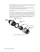
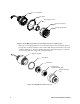
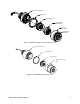
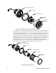
2. At the monitoring site, use #10 screws through the junction box’s two mounting holes
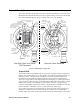
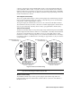
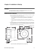
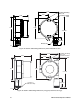
to secure the junction box to a vertical surface. Figure 11 - Figure 17 show the outline
and mounting dimensions for each version of the M2. Mount the M2 with the detector
facing down as shown in the following figures.
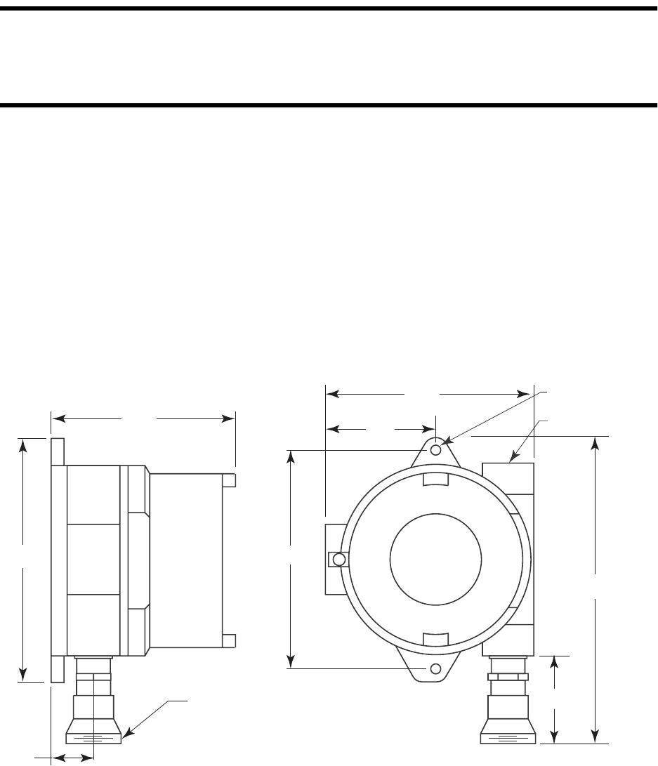
Figure 11: Outline & Mounting Dimensions, Catalytic LEL
4.60
6.10
1
.10
.25 Dia. Mounting
Hole, 2X
3/4 NPT Condu
it
Hu
b
7.7 max
2.75
5.20
1 1/2-20 For
Calibration Cup
2.3 max
5.46