
Operator`s manual

5 • 30-0954RK-200 Series Sample Draw Aspirator Adapter
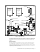
detector head’s cover, and to bring power/signal wiring to the detector head. Also provide
sufficient clearance for routing of sample, compressed air, and exhaust lines.
2. Connect power/signal wiring to the detector head(s) as described in the detector head
operator’s manual.
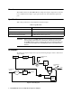
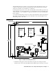
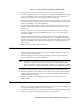
3. Connect a contact monitoring device to the low flow and drain fault contact terminals inside
the low flow and drain fault contact housing using the field wiring cable entry bushing. The
contacts may be wired individually or in parallel. When wired individually, you will need one
monitoring device for each set of contacts. When a specific monitoring device goes into alarm,
you will immediately know which set of contacts closed and what the problem is. When wired
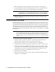
in parallel, only one monitoring device is needed to monitor both sets of contacts. However,
when that device goes into alarm, it will be unclear which set of contacts closed without further
investigation. Wiring diagrams for each scenario are shown below.
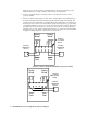
Figure 4: Low Flow and Drain Fault Wiring, Independent Wiring
Contact
Terminal
Block
Drain
Fault
Yellow
Blue
Blue
Factory
Wired
Yellow
Factory
Wired
Low
Flow
Contact
Monitoring
Device
Contact
Monitoring
Device
Contact
Terminal
Block
Yellow
Blue
Blue
Factory
Wired
Yellow
Factory
Wired
Low
Flow
Contact
Monitoring
Device
Drain
Fault