
Operator`s manual

30-0954RK-200 Series Sample Draw Aspirator Adapter • 2
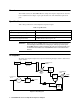
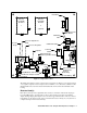
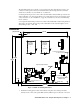
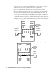
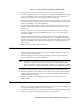
Figure 2: Component Location
The sample draw adapter consists of eleven major components (see Figure 2 ): the detector head (1
or 2), regulator, aspirator, detector adapter, detector chamber (1 or 2), flowmeter, calibration valve,
inlet/blowback valve, low flow switch, drain fault switch, and low flow and drain fault contact
housing.
Detector Head(s)
Each detector head provides a signal that can be used by a controller to indicate the sample gas
level. Any RKI S Series, S2 Series, M2, or direct connect detector head can be used with the
sample drawing adapter plate. Figure 2 above shows the approximate location of the two detector
heads. Please see the detector head operator’s manual of the detector head(s) in your system for a
complete description of the detector head(s).
Calibration
Valve
Calibration Valve
Push Button
Flow Meter
1/4 O.D. Tube Sample Inlet Fitting
Adjustment
Screw
Water Trap
Pressure Adjustment
Knob
Detector
Head with
Chamber
(optional)
Low Flow and Drain
Fault Contact
Housing
Detector
Head with
Chamber
1
OUT
IN
1/4O.D.TubeCompressedAir
Inlet Fitting
Inlet/Blowback Valve Button
Inlet/Blowback
Valve
Aspirator
2
OUT
+
-
Calibration Fitting
Low Flow
Switch
IN
Aspirator/Sample
Exhaust (1/8 NPT female)
Pressure Regulator
Pressure
Gauge
Drain
Fault
Switch