
Operator`s manual
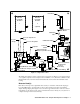
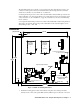

7 • 30-0954RK-200 Series Sample Draw Aspirator Adapter
3. Make sure that all personnel and equipment are clear of the inlet end of the sample line.
4. To operate the blowback valve, press and hold the button on the front of the blowback valve.
As long as the button is held, compressed air will be applied to the sample line.
WARNING: The blowback pressure can be as high as 140 PSI. Make sure that all personnel
and equipment are clear of the sample line inlet end to avoid personal injury or
equipment damage if a sample line obstruction is blown out of the sample line.
5. Release the button on the blowback valve. Verify that the sample is now flowing properly
through the sample line.
Setting the Drain Fault Switch
The drain fault switch is factory set to detect a break in the drain line or very low drain flow from
the water trap during operation. Under normal circumstances, it should not be necessary to adjust
the drain fault switch in the field. If the drain fault switch contacts close to indicate a problem in the
drain line and no cause can be determined, it may be necessary to adjust the drain fault switch. If
the drain fault switch contacts are not operating properly, perform the following procedure to set
the drain fault switch. If the drain fault switch contacts continue to operate improperly, contact RKI
Instruments, Inc.
NOTE: In order to get an accurate open/close reading on the drain fault switch contacts, the low
flow and drain fault switches must not be wired in parallel. Any monitoring device must
also be disconnected from the drain fault switch contacts. Remove any jumpers and
monitoring device wires from the drain fault switch contacts before setting the drain fault
switch.
1. Ensure that the flowmeter reading is 3.0 SCFH.
2. Open the enclosure and connect an ohm meter to the drain fault switch terminals on the
terminal block. Check that the contacts are open during normal operation.
3. Using the regulator, adjust the flow down until the flowmeter reads 1.0 SCFH.
4. Carefully adjust the drain fault switch using the adjustment screw until the contacts just close.
5. Adjust the flow back above 1.0 SCFH with the regulator and repeat step 3 until the contacts
close between 0.8 and 1.0 SCFH. To increase the setpoint, turn the adjustment screw slightly
counterclockwise. To decrease the setpoint, turn the adjustment screw slightly clockwise.
6. Adjust the flow back up above 1.0 SCFH. The contacts should reopen.
7. Adjust the flowrate to 3.0 SCFH.
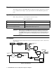
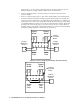
8. Reconnect any wires that were removed before setting the drain fault switch. Refer to Figure 4
and Figure 5 for wiring diagrams.