30-0954RK-200 Series Sample Draw Aspirator Adapter Operator’s Manual Part Number: 71-0188RK Revision: E Released: 5/16/12 www.rkiinstruments.
WARNING Read and understand this instruction manual before operating detector. Improper use of the detector could result in bodily harm or death. Periodic calibration and maintenance of the detector is essential for proper operation and correct readings. Please calibrate and maintain this detector regularly! Frequency of calibration depends upon the type of use you have and the sensor types.
Product Warranty RKI Instruments, Inc. warrants gas alarm equipment sold by us to be free from defects in materials, workmanship, and performance for a period of one year from the date of shipment from RKI Instruments, Inc. Any parts found defective within that period will be repaired or replaced, at our option, free of charge. Parts must be returned to RKI Instruments, Inc. for repair or replacement.
Overview This manual describes the 30-0954RK-200 Series sample draw aspirator adapter. It also describes how to install and use the adapter. A spare parts list at the end of this manual lists replacement parts. Specifications Table 1 lists specifications for the Sample Draw Aspirator Adapter.
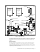
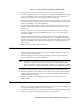
Flow Meter Detector Head with Chamber Detector Head with Chamber 1 2 IN (optional) IN Calibration Valve Push Button OUT OUT Calibration Valve Pressure Adjustment Knob Pressure Gauge Pressure Regulator Aspirator Calibration Fitting Drain Fault Switch Low Flow Switch Aspirator/Sample Exhaust (1/8 NPT female) Adjustment Screw - + Inlet/Blowback Valve Low Flow and Drain Fault Contact Housing Water Trap Inlet/Blowback Valve Button 1/4 O.D. Tube Compressed Air Inlet Fitting 1/4 O.D.
Regulator The regulator has an inlet port on its left side with a 1/4” tube fitting. The maximum allowable inlet pressure is 140 PSI. A gauge at the bottom of the regulator indicates the output pressure. The output pressure, and detector flow, can be adjusted using the knob on the front of the regulator. The detector flow rises or falls as the output pressure is increased or decreased.
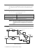
The drain fault switch senses a break or very low flow in the water drain line and provides open contacts in normal operation in the low flow/drain fault contact housing which close when the switch senses a break, a very low drain flow, or a shut down. Connecting monitoring devices to the low flow and drain fault contact terminals provides the user with a notification of a contact closure. Each set of contacts may have their own monitoring device or they may share one.
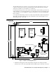
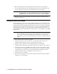
detector head’s cover, and to bring power/signal wiring to the detector head. Also provide sufficient clearance for routing of sample, compressed air, and exhaust lines. 2. Connect power/signal wiring to the detector head(s) as described in the detector head operator’s manual. 3. Connect a contact monitoring device to the low flow and drain fault contact terminals inside the low flow and drain fault contact housing using the field wiring cable entry bushing.
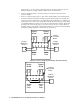
Figure 5: Low Flow and Drain Fault Wiring, Parallel Wiring 4. Start up the detector head(s) as described in the detector head operator’s manual. 5. Connect a sample line from the area to be sampled to the sample inlet fitting at the bottom right of the panel. The fitting accepts 1/4” OD rigid metal tubing such as copper, aluminum, or stainless steel tubing. Be sure to use tubing appropriate for the target gas. 6. The aspirator exhaust includes the sample air.
3. Make sure that all personnel and equipment are clear of the inlet end of the sample line. 4. To operate the blowback valve, press and hold the button on the front of the blowback valve. As long as the button is held, compressed air will be applied to the sample line. WARNING: 5. The blowback pressure can be as high as 140 PSI.
Parts List Table 2 lists replacement parts and accessories for the sample draw adapter. Table 2: Parts List Part Number Description 06-1248RK-03 Tubing, 3/16 x 5/16, polyurethane, 3 foot length, for calibration kit 07-0107RK Gasket for 1/2 NPT type detector adapter 07-7120RK O-ring for replaceable sensor type detector 07-7218RK O-ring, 0.734 ID x 0.139, for 3/4 NPT type detector 07-7225RK O-ring, 1.243 ID x .139, buna, for detector chamber 13-1070RK Captive panel screw, 10-32 x 1.