
Manual


M2 Transmitter Operator’s Manual 22
conduit for connections to the power/signal terminal strip depending on whether
or not the signal (S) terminal is used. The S terminal has a 4 - 20 mA output, but if
you do not need to monitor this signal and do not connect to the S terminal to
access this signal, the M2 will still function completely.
• If the PWR/SIG connections and one or more relays are used, route the
connections to the M2 in conduit. Use shielded cable in the conduit for the PWR/
SIG connections and unshielded cable or individual wires for the relay
connections. Make sure any wire or cable used for relay wiring is appropriately
rated for the power that it will carry.
NOTE: If shielded cable is used for the PWR/SIG connections, leave the cable shield’s
drain wire insulated and disconnected at the M2. You will connect the opposite
end of the cable’s drain wire at the controller or device.
• If the M2 will be wired into a Modbus network, see “Chapter 8: RS-485 Modbus
Output” on page 50.
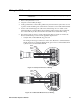
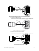
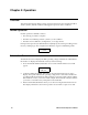
See Figure 26 below for field wiring connections to the M2.
Figure 26: Wiring the M2 to a Controller and Alarm Devices
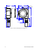
8. Re-install the control PCB (and ribbon cable if necessary). Be sure the ribbon cable is
routed down below the control PCB so it will not be damaged by the cover when it is
screwed back on.
9. Secure the junction box cover to the junction box.
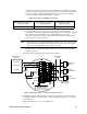
Table 4: Wire Size for PWR/SIG Connections
Max Distance to Controller
w/18 Gauge Wire
Max Distance to Controller
w/16 Gauge Wire
Max Distance to Controller
w/14 Gauge Wire
2,500 ft. 5,000 ft. 8,000 ft.
S
PWR/SIG
+
C NC NO
FAIL
Alarm 1
Alarm Devic
e
Fail Alarm
Device
Alarm Device
Power
A B C
RS 485
ALARM 2
(24 VDC) -
4 - 20 mA In (S)
(24 VDC) +
RKI Controller
Terminals
Typical Alarm
Wiring Shown
Alarm 2
Alarm Devic
e
+
See
Modbus
Wiring
C NC NO
TOXIC OXY
C NC NO
ALARM 1
See
Detector
Wiring