M2 Transmitter Operator’s Manual Part Number: 71-0107RK Revision: L Released: 7/18/14 RKI Instruments, Inc. www.rkiinstruments.
WARNING Read and understand this instruction manual before operating instrument. Improper use of the gas monitor could result in bodily harm or death. Periodic calibration and maintenance of the gas monitor is essential for proper operation and correct readings. Please calibrate and maintain this instrument regularly! Frequency of calibration depends upon the type of use you have and the sensor types.
Product Warranty RKI Instruments, Inc. warrants gas alarm equipment sold by us to be free from defects in materials, workmanship, and performance for a period of one year from date of shipment from RKI Instruments, Inc. Any parts found defective within that period will be repaired or replaced, at our option, free of charge.
Table of Contents Chapter 1: Introduction . . . . . . . . . . . . . . . . . . . . . . . . . . . . . . . . . . . . . . . . . . . . . . . . . . . . . . . 1 Overview . . . . . . . . . . . . . . . . . . . . . . . . . . . . . . . . . . . . . . . . . . . . . . . . . . . . . . . . . . . . . 1 About the M2 Transmitter . . . . . . . . . . . . . . . . . . . . . . . . . . . . . . . . . . . . . . . . . . . . . . . 1 About this Manual . . . . . . . . . . . . . . . . . . . . . . . . . . . . . . . . . . . . . . . . . . .
Chapter 7: Maintenance . . . . . . . . . . . . . . . . . . . . . . . . . . . . . . . . . . . . . . . . . . . . . . . . . . . . . 36 Overview. . . . . . . . . . . . . . . . . . . . . . . . . . . . . . . . . . . . . . . . . . . . . . . . . . . . . . . . . . . . . 36 Preventive Maintenance . . . . . . . . . . . . . . . . . . . . . . . . . . . . . . . . . . . . . . . . . . . . . . . . 36 Troubleshooting . . . . . . . . . . . . . . . . . . . . . . . . . . . . . . . . . . . . . . . . . . . . . . . . . . . . . . .
Chapter 1: Introduction Overview This chapter briefly describes the M2 Transmitter. This chapter also describes the M2 Transmitter Operator’s Manual (this document). Table 1 at the end of this chapter lists the specifications for the M2. About the M2 Transmitter The M2 transmitter is a fixed mount, continuous-monitoring detector head. All user adjustable parameters may be accessed using push button switches.
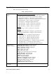
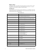
Specifications Table 1 lists specifications for the M2. Table 1: M2 Specifications Target Gas/Detection Range Combustible Gas/Carbon Dioxide (CO2) • Catalytic LEL: 0 - 100% LEL, 1% LEL increments (CH4 calibration unless otherwise specified.
Table 1: M2 Specifications Area Classification Explosion-proof for Class I, Groups B, C, and D (Combustible, CO2, CSA Type CO and H2S, and CSA Type oxygen) Sampling Method Diffusion Input Power 19 - 30 VDC Controls • Three push button switches • Three magnetic switches for non-intrusive calibration Weight 4.5 lbs.
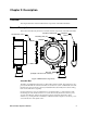
Chapter 2: Description Overview This chapter describes external and internal components of the M2 Transmitter. External Description This section describes the junction box and all external components of the M2 transmitter. 3/4 NPT Conduit Hub Junction Box Cover Mounting Slot (2x) Magnetic Wand Window Detector (Catalytic LEL Detector Shown) Figure 1: M2 External Components Junction Box The M2’s cast aluminum junction box is dust and weather resistant.
Magnetic Wand The magnetic wand is a short plastic rod with a magnet in one end. It is used to actuate the magnetic control switches on the control PCB while the junction box cover is still installed so that non-intrusive calibration can be performed. Gas Detector The gas detector senses the target gas and is mounted in a 3/4” conduit hub on the right bottom side of the M2. A variety of detectors may be used with the M2. Table 2 below lists the detectors that can be used with the M2.
Table 2: M2 Detectors Target Gas, Range Detector(s) Used SO2, 0 - 6 ppm • 65-2300RK-SO2 Catalytic Detectors The catalytic LEL detectors have a 1/2” NPT thread and require a 3/4”NPT x 1/2”NPT reducer to install in the detector hub. The rest of the detectors have a 3/4” NPT mounting thread and are installed directly in the detector hub.
Detector Housing Body Cap Gasket Plug-In Oxygen Sensor Detector Housing Cap Hydrophobic Membrane Figure 3: 65-2494RK Oxygen Detector, Non-Explosion Proof, Capillary Type CO and H2S Detectors Both types of CO and H2S detectors have replaceable plug-in sensors inside the detector housing. The CO detector includes a charcoal filter disk which is held onto the sensor with a rubber retaining boot.
Detector Housing Body Cap Gasket CO Plug-in Sensor Charcoal Filter w/Rubber Boot Detector Housing Cap Hydrophobic Membrane Figure 5: 65-2496RK CO Detector Non-Explosion Proof Detector Housing Body Cap Gasket H2S Plug-in Sensor Spacer Rubber Boot Detector Housing Cap Flame Arrestor Guard Figure 6: 65-2423RK-05 H2S Detector, CSA M2 Transmitter Operator’s Manual 8
Detector Housing Body Cap Gasket H2S Plug-in Sensor Detector Housing Cap Hydrophobic Membrane Figure 7: 65-2495RK H2S Detector Non-Explosion Proof ESM-01 Detectors The construction of the various ESM-01 detectors is similar. Each of the ESM-01 detectors has a different replaceable plug-in sensor that protrudes through the detector housing cap.
Internal Description This section describes the internal components of the M2. The internal components of the M2 include the terminal PCB which provides for all the wiring connections to the M2 and the control PCB which displays the gas reading and has the control buttons.
connector at the bottom of the terminal PCB is used to connect the terminal PCB to the control PCB with a ribbon cable. A 5 position connector on the left side of the terminal PCB is used by factory or field service personnel to program the M2. On the combustible and CO2 versions of the M2, a factory adjust pot just above the programming connector is used to set the detector current.
Relay Terminal Strips The right column of terminal strips consists of, from top to bottom, the fail, alarm 1, and alarm 2 relay terminal strips. They are three-position plug-in style terminal strips. The relay terminal strips are used to connect devices such as lights and horns that are controlled by the relay contacts. The relay contacts are rated at 115 VAC, 5 amps. The relay contacts may also be used to control higher rated relays.
actuate them. Although the magnetic switches have the same functions as the push button switches, it is not practical to use them for operations other than calibration because it is not possible to actuate two magnetic switches at once with only one magnetic wand. Since displaying the Information Screen only requires the use of one switch, the wand may be used to show the Information Screen (see “Information Screen” on page 25).
Chapter 3: Installation & Startup Overview This chapter describes procedures to mount the M2 Transmitter in the monitoring environment and wire it to input power and devices. Mounting the M2 Transmitter 1. 2. Select a mounting site that is representative of the monitoring environment. Consider the following when you select the mounting site. • Select a site where the M2 is not likely to be bumped or disturbed.
4.59 5.00 3/4 NPT Conduit Hub 2.41 5.86 5.23 7.4 max 1.9 max .47 (2X) .30 (2X) 1.02 Figure 12: Outline & Mounting Dimensions, IR Combustible & CO2 4.59 5.00 3/4 NPT Conduit Hub 2.41 5.86 5.23 7.9 max 1 1/2-20 For Calibration Cup 1.02 .47 (2X) 2.6 max .
4.59 5.00 3/4 NPT Conduit Hub 2.41 5.86 5.23 6.5 max 1 1/2-20 For Calibration Cup 1.5 max .47 (2X) 1.02 .30 (2X) Figure 14: Outline & Mounting Dimensions, Replaceable Sensor, Non Explosion Proof, H2S, CO, and Oxygen 4.59 5.00 2.41 5.86 3/4 NPT Conduit Hub 5.23 8.4 max .47 (2X) .30 (2X) 3.2 max 1.
4.59 5.00 3/4 NPT Conduit Hub 2.41 5.86 5.23 10.4 max .47 (2X) 4.82 max .30 (2X) 1.
Wiring the M2 Transmitter WARNING: Always verify that the power source is OFF before making any wiring connections. 1. Remove the junction box cover. 2. Grasp the control PCB by its edges. 3. Gently pull until the control PCB is pulled away from the banana jacks. Take care not to pull too hard and damage the cable which connects the control and terminal PCB’s. 4. Let the control PCB hang by the cable. The terminal strips are now visible on the terminal PCB.
• Oxygen Detector, Partial Pressure, Capillary Type, and CSA Capillary Type The wiring for all the oxygen detectors is the same. White wire to terminal labeled OXY +, green wire to terminal labeled OXY -.
C NC NO ALARM 1 + OXY A A B C RS 485 C NC NO ALARM 2 + TOXIC TOXIC + RS 485 B C White C NC NO FAIL - S + PWR/SIG PWR/SIG - S + OXY + - Green Figure 22: Capillary Type Replaceable Sensor Oxygen Detector Wiring • CSA type CO or H2S gas detector. C NC NO ALARM 1 A C NC NO ALARM 2 B C RS 485 C B A RS 485 TOXIC TOXIC OXY OXY C Red NC NO FAIL PWR/SIG S Black S PWR/SIG Red wire to terminal labeled TOXIC +, black wire to terminal labeled TOXIC -.
• ESM-01 Toxic Detectors Wire Color NC NO FAIL C NC NO ALARM 1 C NC NO ALARM 2 A B C RS 485 C A See Chart B RS 485 TOXIC TOXIC OXY OXY C Black S PWR/SIG PWR/SIG S The ESM-01 toxic detectors have one black wire and one color coded wire. Connect the color coded wire (see chart below) to the terminal labeled TOXIC + and the black wire to the terminal labeled TOXIC -. Gas Type Brown AsH3 Yellow Cl2 Red NH3 Orange NO Green PH3 Blue SO2 Figure 25: ESM-01 Toxic Detector Wiring 6.
conduit for connections to the power/signal terminal strip depending on whether or not the signal (S) terminal is used. The S terminal has a 4 - 20 mA output, but if you do not need to monitor this signal and do not connect to the S terminal to access this signal, the M2 will still function completely. Table 4: Wire Size for PWR/SIG Connections Max Distance to Controller w/18 Gauge Wire 2,500 ft. Max Distance to Controller w/16 Gauge Wire 5,000 ft. • 8,000 ft.
10. Make controller, device, and relay connections as appropriate. If shielded cable is used for the PWR/SIG connections, connect the cable shield’s drain wire to an available chassis ground at the gas monitoring controller, recording device, or programmable controller. Start Up Introducing Incoming Power 1. Complete the installation procedures described earlier in this manual. 2. Verify that all wiring connections are correct and secure. 3. Turn on the incoming power. 4.
removing the wand is the same as pressing and releasing a button. Touching the glass and keeping the wand in place is the same as pressing and holding a button. WARNING: NOTE: The M2 is not an active gas monitoring device during the fresh air adjustment procedure. The 4-20 mA output signal will “freeze” at 3.5 mA for a toxic, combustible gas, or CO2 M2, or at 17.4 mA for an oxygen M2, and all relays will remain in their non-alarm state while the M2 is in Calibration Mode.
Chapter 4: Operation Overview This chapter describes the M2 in normal operation. This chapter also describes the M2 in alarm 1, alarm 2, and fail conditions and suggests responses to these conditions. Normal Operation Normal operation is defined as follows: • The start-up procedure is complete. • The M2 is not indicating an alarm 1, alarm 2, or fail condition. • The M2 is not in Calibration, Configuration, or Gas Type modes.
4 - 20 mA Signal Output Operation The output at the S terminal of the power/signal terminal strip is a 4 - 20 mA signal that corresponds to the detection range of the M2. During normal operation, this signal tracks the gas concentration on the LCD. There are several circumstances where the signal output will not track the display reading but will behave as follows: • When the M2 is in its warm-up period, the signal output will be fixed at 3.5 mA (zero) for all gas types except oxygen.
Table 5: Visual and Audible Alarm Indications Condition Cause Visual Indication(s) Fail • Disconnected or misconnected detector wiring • Display reading at -10% of full scale or lower • Defective components • F LED is on • FAIL message replaces gas reading NOTE: There is a 30 second delay on the fail condition. Low Power DC power source less than 18.5 volts.
Alarm 2 Condition Alarm 2 Condition Indications When the gas reading reaches the alarm 2 setpoint, the M2 senses an alarm 2 condition. The M2 alerts you to an alarm 2 condition as follows: • The A2 LED turns on. • The gas reading alternates with the ALARM-2 message. • The alarm 2 relay energizes. NOTE: If the M2 is in both an alarm 1 and alarm 2 condition, both the A1 and A2 LEDs will be on, the gas reading will alternate with the ALMS 1&2 message, and both alarm relays will energize.
Low Power Alarm Low Power Alarm Indications The M2 senses a low power condition when the DC power source is 18.5 volts or less. WARNING: While in a low power condition, the M2 is not an active gas monitor. When the M2 senses a low power condition, it alerts you as follows: • The F LED turns on. • The message LowPower is indicated on the top line of the LCD and the input voltage is displayed on the bottom line of the LCD. • The fail relay de-energizes.
Chapter 5: Configuration Mode Overview This chapter describes how to view and change M2 parameters using Configuration Mode. It is accessed using the program buttons. Configuration Mode includes a 5-minute time-out feature. If you do not press a control button for 5 minutes, the M2 automatically returns to normal operation. NOTE: If the M2 returns to normal operation because of a time-out, it enters a warmup period just as it does when it is first turned on.
Table 6: Configuration Parameters Parameter (Factory Set Value) Description ALARM-1 (level) (See “M2 Specifications” on page 2) The gas reading at which the M2 initiates an alarm 1 condition. ALARM-1 (activation) (Decrease for oxygen M2, Increase for all other types) Indicates if the alarm 1 circuit is activated by gas readings increasing (Increase) or decreasing (Decrease) to the ALARM-1 Level. ALARM-1 (relay action) (N. DE-EN) If set as N.
Table 6: Configuration Parameters (Continued) Parameter (Factory Set Value) Description ZeroSupp (0.0% of the detection range in terms of the detection units for carbon dioxide channel types, 0.5% oxygen for oxygen types, 2% of the detection range in terms of the detection units for all other types) The zero suppression feature helps prevent “jumpy” readings near the fresh air reading. For example, if the zero suppression setting for a combustible LEL detector is 2.
Chapter 6: Gas Type Mode Overview This chapter describes how to use Gas Type Mode to select the M2’s gas type. The gas type determines the target gas and detection range. The combustible gas/CO2 and toxic/ oxygen M2s have a different terminal PCB and run on different firmware. Your M2 will only have gas type choices available that it can support. Gas Type Mode includes a 5-minute time-out feature. If you do not press a button for 5 minutes, the M2 automatically returns to normal operation.
Table 7: Combustible Gas/CO2 Gas Types Gas Type Choices Detection Range CO2 0 - 5,000 ppm CO2 0 - 2,000 ppm CO2 0 - 100% volume CO2 0 - 50.0% volume CO2 0 - 5.00% volume NH3 0 - 5.00% volume NH3 0 - 2.00% volume Table 8: Toxic/Oxygen Gas Types Gas Type Choices Detection Range H2S 0 - 100 ppm CO 0 - 300 ppm OXYGEN 0 - 25.0% volume SIH4 0 - 15.0 ppm PH3 0 - 1.00 ppm O3 0 - 1.00 ppm NO 0 - 100 ppm HF 0 - 9.00 ppm HCN 0 - 15.0 ppm HCL 0 - 15.0 ppm H2SE 0 - 5.
Table 8: Toxic/Oxygen Gas Types Gas Type Choices NOTE: Detection Range CL2 0 - 3.00 ppm CL2 0 - 10.0 ppm Consult factory for availability of detectors for toxic M2 types not listed in “M2 Specifications” on page 2. 4. When the desired target gas is on the display, press and release the ENTER button. The display will ask SAVE IT? YES/NO. 5. To discard the gas type change, press and release the DOWN/NO button. The display will ask DO OVER? YES/NO. Press the DOWN/NO button.
Chapter 7: Maintenance Overview This chapter describes procedures for performing preventive maintenance, troubleshooting, calibrating the M2, and replacing field replaceable parts. It includes separate procedures for calibrating the combustible gas/CO2/toxic and oxygen versions of the M2. Preventive Maintenance This section describes a recommended preventive maintenance schedule to ensure the optimum performance of the M2. It includes daily, monthly, and quarterly procedures.
NOTE: When applying gas to an NH3 ESM-01, the 0.25 LPM flowrate regulator must be used. All other M2s require a 0.5 LPM flowrate regulator. 5. Screw the calibration gas cylinder into (onto for an H2S cylinder) the fixed flow regulator. 6. Turn the regulator knob counterclockwise to open the regulator. 7. Allow calibration gas to flow for one minute. 8. Verify that the display reading is within ± 20% of the gas concentration.
Troubleshooting The troubleshooting guide describes symptoms, probable causes, and recommended action for problems you may encounter with the M2. NOTE: This troubleshooting guide describes M2 problems only. If the M2 is connected to a controller, see the controller operator’s manual for problems you may encounter with the controller.
Table 9:Troubleshooting the Combustible Gas Detector (Continued) Condition Symptom(s) Probable Causes Recommended Action Fail Condition • M2 indicates a fail condition. • Controller indicates a fail condition • The detector wiring to the terminal PCB is disconnected or misconnected. • The wiring from the M2 to the controller is disconnected or misconnected. • The detector fresh air signal is low enough to cause a fail condition. • The detector is malfunctioning.
Calibration Frequency Some M2s have IR (infrared) type detectors, such as an M2 for CO2 or an LEL M2 with an IR detector. Most of the M2s do not have an IR detector. For example, an H2S M2 has an electrochemical detector and some of the combustible M2s use catalytic detectors. The M2s that use IR detectors typically need less frequent calibration as is discussed below. See Table 1, “M2 Specifications,” on page 2 to see which M2s are IR versions.
NOTE: While in the calibration program, if there is no switch activity for the calibration time-out period the unit will return to normal operation. See “Viewing & Changing M2 Parameters” on page 30 for instructions to set the calibration time-out. NOTE: The following procedure assumes that the target gas is present in a high enough concentration to affect the fresh air (zero) reading.
Adjusting the Fresh Air Reading 1. While in normal operation, press and hold the UP/YES button for 5 seconds to enter Calibration Mode. Release the button when the following screen appears. Calib? YES/NO 2. If you want to continue with calibration, press and release the UP/YES button. The display will indicate the target gas and CAL Mode for a few seconds before showing FreshAir Adjust?. If you want to exit Calibration Mode, press and release the DOWN/NO button.
6. Unscrew the calibration gas cylinder from the fixed flow regulator and unscrew the calibration cup from the detector. For an ESM-01 detector, pull the calibration cup off of the ESM-01 sensor and screw the splashguard back onto the detector housing cap. The M2 will continue to display the maximum gas response on the display and retain the response level in its memory. 7.
NOTE: While in calibration mode, if there is no switch activity for the calibration timeout period the unit will return to normal operation. See “Viewing & Changing M2 Parameters” on page 30 for instructions to set the calibration time-out. NOTE: The following procedure assumes that the oxygen concentration in the calibration area is not normal, 20.9%, but is oxygen deficient.
oxygen reading will be on the bottom display line. To skip adjusting the fresh air reading, press and release the DOWN/NO button. The display will indicate ZERO w/Cal Gas?. Skip to the next section, “Adjusting the Zero Setting”. 4. Screw the zero air cylinder into the fixed flow regulator. 5. Turn the regulator knob counterclockwise to open the regulator. 6. Allow zero air to flow for 2 minutes. If the oxygen concentration in the area is less than 20.9, the reading should stabilize after 2 minutes. 7.
9. The display will now alternate between the normal operation screen and the message REMOVE CAL GAS for 1 minute. If the calibration gas has not been removed from the detector remove it now to avoid unwanted alarms. During this 1 minute period, the signal output will remain fixed at 17.4 mA and the relays will remain in their non-alarm state to avoid unwanted alarms while the calibration gas clears from the detector.
• Oxygen gas detector. Green wire to terminal labeled OXY +, white wire to terminal labeled OXY -. 11. Re-install the detector terminal strip into its socket. 12. Re-install the control PCB (and ribbon cable if necessary). Be sure the ribbon cable is routed down below the control PCB so it will not be damaged by the cover when it is screwed back on. 13. Secure the junction box cover to the junction box. 14. Turn on or reconnect power to the M2.
Replacing the CO Sensor Charcoal Filter The charcoal filter is used to scrub out interfering gases from the environment being monitored, such as H2S and certain hydrocarbons. If you are experiencing unexplained upscale readings on a CO M2, the charcoal filter may be saturated and no longer scrubbing out interfering gases and it may be necessary to change the charcoal filter. 1. Turn off or disconnect power to the M2. 2. Unscrew the detector housing cap from the housing body.
WARNING: 5. Make sure the cap gasket is in place and screw the detector cap back onto the housing body. If the splash guard was unscrewed from the detector cap, screw it back onto the detector cap. 6. Turn on or reconnect power to the M2. NOTE: 7. 49 The ESM-01 detectors cannot be changed from one type to another. Replace the plug-in sensor only with the same type of ESM-01 sensor. Allow the replacement sensor to warm up for 15 minutes before you continue with the next step.
Chapter 8: RS-485 Modbus Output Overview This chapter describes the M2’s RS-485 Modbus output and how to configure the M2 to make use of it. It also discusses how to wire the M2 into a Modbus system. The M2 provides an RS-485 serial communications interface. It is a Modbus Slave Device, supporting 2-wire RS-485 Modbus RTU serial communications. Wiring the M2 in a Modbus System The M2 is a 2-wire Modbus RTU device.
NC NO FAIL C NC NO ALARM 1 C NC NO ALARM 2 TOXIC To Additional M2s A B C RS 485 C NC NO ALARM 2 See Detector Wiring A B C RS 485 Input Common D1 Terminals D0 TOXIC See Detector Wiring C S PWR/SIG OXY NC NO FAIL C NC NO ALARM 1 C S PWR/SIG 24 VDC OXY Power Supply Modbus Controller Figure 27: Recommended Modbus Wiring Alternate Modbus Wiring For Existing Installations Although the wiring shown in Figure 27 is recommended, it is possible to wire the M2 into a Modbus system with only 4 wir
Termination Jumper The M2 includes a 2-pin termination header (see Figure 9) that is used when the M2 is used in a Modbus system. Every M2 is supplied with a termination jumper (a jumper block) installed onto this header. If the M2 is not used in a Modbus system, this jumper has no function. When the M2 is installed in a Modbus system, this jumper must be installed in an M2 that is at the end of a Modbus line.
Using the M2 in a 4-wire Modbus System Although the M2 is a 2-wire Modbus RTU device, it can be used with a 4-wire Modbus controller if the system wiring is modified as follows: • Connect the controller’s TxD0 and RxD0 wires together and use this connection as the 2-wire Modbus D0 signal. • Connect the controller’s TxD1 and RxD1 wires together and use this connection as the 2-wire Modbus D1 signal.
Table 11: Configuration Parameters Modbus Mode Parameter Available Settings & Description Enabled/Disabled Can be set to ENABLED or DISABLED (factory setting). Enables or disables the Modbus output. Slave ID The Slave ID can be set to values from 1 (factory setting) to 247. The M2 will only receive messages from the Master which are addressed to this Slave ID (except for broadcast messages which are received by all slaves).
Supported Modbus Functions The M2 supports Function Code 03: Read Holding Registers and Function Code 16: Write Registers. The register assignments detailed below were implemented in M2 firmware version 5.0. Please see revision B of the M2 manual if you have an M2 with a firmware version previous to 5.0. WARNING: Do not attempt to use registers according to the instructions below with units that have firmware versions previous to 5.0. For the Modbus register assignments of M2s with firmware previous to 5.
Table 13: Register 2, Operating State, Alarms & Relays Bit & Field Assignments (Continued) Bit(s) Value [11] Gas Type Change 0=Not Changed 1=Changed [10] Configuration Change 0=Not Changed 1=Changed [9] Calibration Activity Flag 0=No Calibration Activity 1=Calibration Activity Has Occurred [8] Fail Status 0 = Fail Not Asserted 1 = Fail Asserted [7:6] Alarm 2 Status 0 = No Alarm 1 = Unacknowledged Alarm 2 = Acknowledged Alarm 3 = Unused Code [5:4] Alarm 1 Status 0 = No Alarm 1 = Unacknowledged A
Register 12 Register 12 is the range (full scale readout). Register 13 Register 13 is the alarm 1 set point. The decimal point location is the same as specified in Register 1. Register 14 Register 14 is the alarm 2 set point. The decimal point location is the same as specified in Register 1. Registers 15 - 19 Registers 15 - 19 are the Gas Name ASCII String (NULL Terminated). Registers 20 - 22 Registers 20 - 22 are the Gas Units String (NULL Terminated). Register 23 Register 23 is the alarm 1 trigger.
Register 30 Register 30 is the alarm 2 relay reset. 0=Latching 1=Self-Resetting Register 31 Register 31 is the alarm 2 ON delay. Integer values are in seconds. Register 32 Register 32 is the alarm 2 OFF delay. Integer values are in seconds. Register 33 Register 33 is zero suppression. Toxics and LEL: 0%-6% of full scale Oxygen: 0%-0.7% Oxygen The decimal point location is the same as specified in Register 1. Register 34 Register 34 is noise filter. Integer values in seconds. 0-60 in 5 second increments.
14=Operation Not Performed Register 39 Register 39 is the auto-zero disable. 0=AutoZero Enabled 1=AutoZero Disabled Register 40 Register 40 is the remote configuration register access level 0=None 1=Alarm Reset Function Code 16: Write Registers There are 21 registers in Function Code 16 that can be used to write to the M2. This manual only describes Register 16 because it can be used to reset an alarm condition. For a complete description of Function Code 16, request Appendix C from RKI Instruments, Inc.
Parts List Table 15 lists replacement parts and accessories for the M2 Transmitter. Table 15: Parts List Part Number Description 06-1248RK Calibration kit sample tubing (3/16 in. x 5/16 in.
Table 15: Parts List Part Number 61 Description 65-2300RK-NH3 ESM-01 detector, 0 - 75.0 ppm ammonia 65-2300RK-NO ESM-01 detector, 0 - 100 ppm nitric oxide 65-2300RK-PH3 ESM-01 detector 0 - 1.00 ppm phosphine 65-2300RK-SO2 ESM-01 detector, 0 - 6.
Table 15: Parts List Part Number Description 81-0073RK-03 Calibration cylinder, CO2, 15% in nitrogen, 103 liter steel 81-0076RK-01 Zero air calibration cylinder, 34 liter steel 81-0076RK-03 Zero air calibration cylinder, 103 liter steel 81-0078RK-01 Calibration cylinder, 100% nitrogen, 34 liter steel (used for setting oxygen zero) 81-0078RK-03 Calibration cylinder, 100% nitrogen, 103 liter steel (used for setting oxygen zero) 81-0151RK-02 Calibration cylinder, H2S, 25 ppm in nitrogen, 58 liter
Table 15: Parts List Part Number 63 Description ES-1531-CO CO sensor, plug-in ES-1537-H2S H2S sensor, plug-in ESM-015-NO ESM-01 plug-in sensor, 0 - 100 ppm nitric oxide ESM-01DH-ASH3 ESM-01 plug-in sensor, 0 - 1.50 ppm arsine ESM-01DH-D-SO2 ESM-01 plug-in sensor, 0 - 6.00 ppm sulphur dioxide, diffusion type only ESM-0DH-PH3 ESM-01 plug-in sensor, 0 - 1.00 ppm phosphine ESM-01R-D-NH3 ESM-01 plug-in sensor, 0 - 75.0 ppm ammonia, diffusion type only ESM-K01-D-CL2 ESM-01 plug-in sensor, 0 - 3.
Appendix A: Control Button Quick Reference Guide The M2’s control buttons allow access to operational modes, resetting of alarms, and display of the Information Screen. Table 16 shows which button combinations perform these functions and which parameters are available for adjustment while in the operational modes. While in these modes, display prompts showing a “?” require you to respond by pressing either the UP/YES (for yes) or DOWN/NO (for no) button.
Appendix B: PLC and DCS Device Wiring The M2 can be wired to a PLC or DCS device if desired. 1. Guide multi conductor shielded cable or cables or wires in conduit through the top conduit hub of the junction box. The number of cables or wires needed will depend on whether any relays are used and whether the Modbus output is used.
See Figure 31 below for field wiring connections to the M2.
Appendix C: Function Code 16 Registers The M2 supports Function Code 16 that allows writing to the M2. There are 21 registers in this Function Code. The register assignments detailed below were implemented in M2 firmware version 5.0. Please see revision B of the M2 manual if you have an M2 with a firmware version previous to 5.0. WARNING: Do not attempt to use registers according to the instructions below with units that have firmware versions previous to 5.0.
Register 9 Register 9 is the alarm 2 relay state. 0=Normally De-Energized 1=Normally Energized Register 10 Register 10 is the alarm 2 relay reset. 0=Latching 1=Self-Resetting Register 11 Register 11 is the alarm 2 ON delay. Integer value is in seconds. Register 12 Register 12 is the alarm 2 OFF delay. Integer value is in seconds. Register 13 Register 13 is the zero suppression. Toxics and LEL: 0%-6% Full Scale Oxygen: 0%-0.7% Oxygen Value must be an integer. Any decimals are omitted.
Register 19 Register 19 is for clearing change flags. When parameters are changed at the M2, a flag is raised at the controller. This register can be used to clear those flags. Table 18: Register 19, Clear Change Flags Bit(s) Value & Field [15:2] Unused [1] Write “1” to this bit to clear “Gas Type Changed” flag [0] Write “1” to this bit to clear “Configuration Changed” flag Register 20 Register 20 is the AutoZero Disable.