Instruction Manual Inert Gas Testing Eagle with Two Pumps Portable Multi-Gas Detector Part Number: 71-0288RK Revision: P2 Released: 11/12/13 www.rkiinstruments.
WARNING Read and understand this instruction manual before operating instrument. Improper use of the gas monitor could result in bodily harm or death. Periodic calibration and maintenance of the gas monitor is essential for proper operation and correct readings. Please calibrate and maintain this instrument regularly! Frequency of calibration depends upon the type of use you have and the sensor types.
Warranty RKI Instruments, Inc. warranties gas alarm equipment manufactured by RKI and sold by RKI to be free from defects in materials and workmanship for a period of one year from date of shipment from RKI Instruments, Inc. Any parts found defective within that period will be repaired or replaced, at our option, free of charge. This warranty does not apply to items that are subject to deterioration or consumption in normal service, and which must be cleaned, repaired, or replaced routinely.
Table of Contents Introduction . . . . . . . . . . . . . . . . . . . . . . . . . . . . . . . . . . . . . . . . . . . . . 1 Overview . . . . . . . . . . . . . . . . . . . . . . . . . . . . . . . . . . . . . . . . . . . . . . . . . . . 1 About this Manual . . . . . . . . . . . . . . . . . . . . . . . . . . . . . . . . . . . . . . . . . . . 2 Specifications. . . . . . . . . . . . . . . . . . . . . . . . . . . . . . . . . . . . . . . . . . . . 3 Description . . . . . . . . . . . . . . . . . . . . . . . . . . .
Display Mode . . . . . . . . . . . . . . . . . . . . . . . . . . . . . . . . . . . . . . . . . . 20 User and Station ID Screen . . . . . . . . . . . . . . . . . . . . . . . . . . . . . . . . . . . Peak Screen. . . . . . . . . . . . . . . . . . . . . . . . . . . . . . . . . . . . . . . . . . . . . . . . . Elapsed Time Screen . . . . . . . . . . . . . . . . . . . . . . . . . . . . . . . . . . . . . . . . . TWA/STEL Screen . . . . . . . . . . . . . . . . . . . . . . . . . . . . . . . . . . . . . . . . . .
Calibration . . . . . . . . . . . . . . . . . . . . . . . . . . . . . . . . . . . . . . . . . . . . . 42 Calibration Supplies and Equipment . . . . . . . . . . . . . . . . . . . . . . . . . . . 42 Preparing for Calibration . . . . . . . . . . . . . . . . . . . . . . . . . . . . . . . . . . . . . 42 Calibrating the Eagle . . . . . . . . . . . . . . . . . . . . . . . . . . . . . . . . . . . . . . . . 43 Maintenance. . . . . . . . . . . . . . . . . . . . . . . . . . . . . . . . . . . . . . . . . . . .
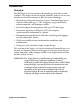
Introduction Overview The RKI Eagle is the most advanced portable gas detection system available. The Eagle is built for rugged reliability and ease of use and includes the latest innovations in gas detection technology: • Simultaneous detection of one to six gases. Standard target gases include combustible gas (% LEL and ppm), oxygen deficiency, carbon monoxide, and hydrogen sulfide. • Powerful sample-drawing pump with up to 125-foot range.
About this Manual This manual is intended for use with the Eagle. Examples used in this manual are for a standard four-gas model (combustible gas, oxygen, carbon monoxide, and hydrogen sulfide). This manual is organized as follows: • The standard sections included in pages 1 through 54 describe the Eagle’s specifications and internal and external components. These sections also describe the operation, calibration, and maintenance of the Eagle.
Specifications Table 1 lists physical and environmental specifications for the Eagle. Table 2 lists specifications for the Eagle’s sensors. Table 1: Eagle Specifications Target Gases Combustible gas; Oxygen (O2), Carbon monoxide (CO); Hydrogen sulfide (H2S)2 Case High-impact polycarbonate-polyester blend Dimensions 10.5 in. x 5.9 in. x 7.0 in. (26.7 cm x 15.0 cm x 17.8 cm) Weight 5 lbs. (2.
Table 2 lists specifications for the Eagle’s sensors. Your Eagle model may not include all of the sensors listed below. The alarm settings are user-adjustable (see “Updating the Alarm Point Settings” on page 33). Table 2: Standard Sensor Specifications Combustible Gas (%LEL1) Combustible Gas (PPM2) Range 0 to 100% LEL Alarm 1 Alarm 2 Oxygen Hydrogen Sulfide Carbon Monoxide Depends on target gas4 0 to 40% O2 0 to 100 ppm 0 to 300 ppm 10% LEL 5000 ppm 19.5% O2 (decreasing) 10.
Description Case The Eagle has a plastic case with a full-sized handle. The highvisibility case is shielded to reduce radio frequency and electromagnetic interference (RFI/EMI). The system is light-weight and balanced, which makes the Eagle easy to carry and use for extended periods. A foam rubber gasket between the top and bottom case components is water- and dust-resistant. You can set the case into 2.5 in. of water without damage. Control Panel The control panel is at the top of the Eagle.
Alarm Lights Two ultra-bright, red, light-emitting diodes (LEDs) provide visual alarms for gas concentrations and malfunctions. They are mounted on the top rear of the case for greatest visibility. Battery Charger Connector The battery charger connector is mounted on the top right rear of the case. The external battery charger connects to this connector to recharge nickel-cadmium (Ni-Cd) batteries. The continuous operation adapter also connects to the battery charger connector.
Hose and Probe A 5 foot polyurethane sample hose and a 10 inch hydrophobic probe are included as standard. The hose has a male quick connect fitting on one end and a female quick connect fitting on the other end. The probe has a male quick connect fitting. Normally, the male end of sample hose is installed in the Eagle inlet fitting and the probe is installed in the female end of the hose.
approximately two years. Combustible Gas Sensor The combustible gas (LEL) sensor is mounted with the flame arrestor down in the sensor block to allow the sample flow to diffuse into the sensor. Five pins extend from the top of the sensor. The sensor cable connects to the pins on one end and terminates in a four-position connector, which plugs into the COMB socket on the analog print circuit board (PCB). The LEL sensor detects combustible gas and vapors in the atmosphere with a catalytic platinum element.
ZERO and SPAN controls. A bracket secures the sensor/amplifier assembly to the instrument case. A flow adapter connected to the sensor allows the sample to flow through the H2 compensated CO sensor. A seven-position connector plugs into the EC4 (channel 4) socket on the analog PCB. The sensor uses a fourth electrode to “null” (compensate) for hydrogen interference. Hydrogen concentrations less than 5000 ppm (approximately 12 %LEL) will not produce a response on this CO sensor.
Operation The Eagle has four operating modes: normal operating mode, display mode, setup mode, and calibration mode. This section describes the Eagle in normal operating mode. It includes procedures to start up the Eagle, set various detection options for the combustible gas channel, and shut down the Eagle. NOTE: The screens illustrated in this section are intended as examples only. The screens displayed by your Eagle model may be slightly different. Starting Up the Eagle 1.
The Battery Voltage screen displays the minimum usable and actual battery voltage (for example, 6.0V). If the battery voltage is too low, the Eagle will not continue. NOTE: The following screen only displays if the data logging option is installed. If the data logging option is not installed, the Self Diagnosis screen displays after the Battery Voltage screen. This message displays the date and time as set in Setup mode.
4. Verify that the Eagle is operating correctly. Use the RKI Check Kit to easily verify correct operation of the Eagle. WARNING: If the Eagle does not respond to verification, take it to a known “fresh-air” environment, then perform the demand zero procedure described in “Preparing for Calibration” on page 42. Repeat step 4 before using the Eagle in a potentially hazardous location.
to determine the response of other combustible gases. This table is based on Eagles in full response mode (methane elimination switch set to CH4) calibrated to methane. Multiply the display reading by the factor in the appropriate column in the table. For example, if you are detecting hexane and the display reads 10% LEL, the actual hexane reading is 10% x 2.14 = 21% LEL hexane. WARNING: The Eagle’s alarms are initiated by the DISPLAY reading not the FACTORED reading.
Setting User Access The CAL/SETUP switch controls the Eagle functions available to the user. The switch setting does not affect the Eagle’s ability to display gas readings and indicate gas and malfunction alarms. 1. Turn off the Eagle. 2. Unscrew the two large screws on the top of the case. 3. Turn over the top half of the case, and locate the CAL/SETUP switch (SW2) near the middle along one edge of the main processor board.
Alarms Alarm Indications This section describes the Eagle’s audible and visual alarm indications for gas, over range, low flow, low battery, and sensor failure alarms. This section also describes how to reset gas alarms. The default alarm settings are listed in Table 2, “Standard Sensor Specifications” on page 4. The alarm settings are user-adjustable as described in “Updating the Alarm Point Settings” on page 33. NOTE: The screens illustrated in this section are intended as examples only.
STEL Alarm (Toxics Only) If a toxic gas channel’s average gas reading for the past 15 minutes exceeds the STEL alarm setting: CH4 OXY H2S CO 0 20 . 9 15 . 0 0 LEL% VOL% PPM S T E L PPM • STEL displays in the alarm field for that channel. • The channel’s display line flashes. • The buzzer sounds a pulsed tone. • The alarm lights flash. TWA Alarm (Toxics Only) If a toxic gas channel’s average gas reading for the past 8 hours exceeds the TWA alarm setting: CH4 OXY H2S CO 0 20 . 9 10 .
Low Flow Alarm If the Eagle’s sample system becomes restricted or blocked (for example plugged probe, fouled filter, pinched tubing): FA I L L OW F L OW LEVE L • The message FAIL LOW FLOW LEVEL replaces the normal screen. • The buzzer sounds a steady tone. • The alarm lights are on continuously. • The pump automatically shuts off to prevent damage. Correct the flow blockage. Press the RESET/SILENCE button to turn off the alarms and restart the pump.
Sensor Failure Alarm and Emergency Operation The Eagle continuously monitors itself for proper operation. If a malfunction occurs, the Eagle alerts you with audible and visual alarms. If a sensor fails during start-up or normal operation: < < FA I L S E N SOR >< OXY > > >< • The message FAIL SENSOR displays. • The failed sensor displays in parenthesis. • The buzzer sounds a steady tone. • The alarms lights flash.
Resetting Gas Alarms You can set the Eagle’s gas alarms for latching or self-resetting alarms (see “Updating the Alarm Latching Setting” on page 35). Self-Resetting Alarms Self-resetting alarms automatically shut off and reset when the gas reading falls below (or rises above for oxygen) the alarm setting. You cannot silence or reset self-resetting alarms. Latching Alarms You can set latching alarms with or without Alarm Silence (see “Updating the Alarm Silence Setting” on page 35).
Display Mode The Eagle has four operating modes: normal operating mode, display mode, setup mode, and calibration mode.
To enter a user and station ID: To scroll to the next screen at any time, press the DISP/ADJ button. 1. Press the POWER/ENTER button. The first character under USER ID flashes (* is default). 2. Press the AIR/▲ and SHIFT/▼ buttons to scroll through the available characters. (The asterisk and blank space are between the set of letters and numbers.) 3. When the desired character displays, press the POWER/ENTER button to enter the character and go to the next character. 4.
TWA/STEL Screen The TWA/STEL screen displays the time-weighted average (TWA) and the short-term exposure limit (STEL) readings for toxic gases only. The TWA reading is the average reading during the last 8 hours. If 8 hours have not elapsed since the last time the TWA/STEL reading was cleared, the average is still calculated over 8 hours. The missing time is assigned a 0 value for readings. The STEL reading is the average reading during the last 15 minutes. T WA H2S CO 0 . 0 0 STEL 0 .
Clear Data Logger Screens CAUTION: Once you clear the data logger, you cannot retrieve any data previously stored in the data logger. The Clear Data Logger screens allow you to clear the data logger storage to accept new data. (Press the DISP/ADJ button to go to the Remaining Log Time screen). You can set the Eagle to overwrite the oldest data when the data log is full (see page 38). C L E AR D A T A L OGG E R ? YES : A I R NO : D I SP L A Y To clear the data log: 1.
Setup Mode NOTE: The screens illustrated in this section are examples only. The screens displayed by your Eagle model may be slightly different. The Eagle has four operating modes: normal operating mode, display mode, setup mode, and calibration mode. This section describes the setup mode.
• To exit setup mode, from the main menu place the prompt next to the last menu option, START MEASUREMENT, then press the POWER/ENTER button. The Eagle begins its normal start-up sequence. Entering Setup Mode WARNING: The Eagle does not detect gas or display readings while in setup mode. The CAL/SETUP switch (SW2) must be in the ON position to enter setup mode. 1. Take the Eagle to a non-hazardous location, and turn the power off. 2.
Updating Channel Settings This procedure describes how to update channel settings for the combustible gas, oxygen, and toxic gas channels. CAUTION: Verify that the correct sensor is installed before you update a channel’s settings. Updating Combustible Gas Channel Settings This section describes how to update the target gas label, set a custom gas label, and update the fullscale PPM setting for the combustible gas channel. Updating the Target Gas Label 1.
The number in parenthesis indicates the display increment for that portion of the PPM range. In the example below, the PPM reading would display in increments of: • 5 from 0 to 100 ppm • 10 from 100 to 1000 PPM • 50 from 1000 to 10,000 PPM • 250 from 10,000 to 50,000 PPM > * * * 50000 PPM 100 ( 5 ) 10000 1000 ( 10 ) 50000 ( ( 50 250 ) ) If you entered a label other than ***, continue with step 6. If you entered ***, go to the next section, “Setting a custom target gas label.” 6.
setting. The fullscale setting flashes. The maximum fullscale setting for the combustible gas channel is 50,000 PPM; the minimum setting is 1000 ppm. The default setting is 50,000 ppm. 2. Press the AIR/▲ and SHIFT/▼ buttons to display the desired fullscale setting (see Table 5), then press the POWER/ENTER button to enter the setting. The prompt flashes.
Updating Oxygen Channel Settings This section describes how to update the target gas label, fullscale setting, and display increment setting for the oxygen channel. Updating the Target Gas Label 1. From the main menu, select the GAS COMBINATIONS menu option. > CH4 OXY H2S CO 2. Use the AIR/▲ or SHIFT/▼ button to place the prompt next to the oxygen channel (in this example OXY). 3. Press the POWER/ENTER button. The oxygen target gas label flashes. This indicates that this setting can now be updated. 4.
Updating the Display Increment Setting 1. Press the SHIFT/▼ button to place the prompt in the third line, then press the POWER/ENTER button. The display increment setting flashes. The allowable settings are 0.2 VOL% (default) and 0.5 VOL%. 2. Press the AIR/▲ or SHIFT/▼ button to display the desired display increment setting, then press the POWER/ENTER button to enter the setting. The prompt flashes. Returning to the Main Menu 1. Press the SHIFT/▼ button. The ESCAPE message displays.
5. Press the AIR/▲ or SHIFT/▼ buttons to display the available target gas labels for the toxic gas channel (H2S, CO, SO2, Cl2, NH3, CO2 (5.00%), CO2 (10000 PPM), CO2 (5000 PPM), ***, and NOT USED). 6. Press the POWER/ENTER button to enter the new target gas label. If you entered a label other than ***, continue with step 7. If you entered ***, go to the next section, “Setting a custom target gas label.” 7.
Updating the Display Increment Setting 1. Press the SHIFT/▼ button to place the prompt in the third line, then press the POWER/ENTER button. The display increment setting flashes. The minimum display increment setting is 0.1 PPM; the maximum display increment setting is 2.5 PPM. 2. Press the AIR/▲ and SHIFT/▼ buttons to display the desired display increment setting, then press the POWER/ENTER button to enter the setting. The prompt flashes. Returning to the Main Menu 1. Press the SHIFT/▼ button.
Updating the Alarm Point Settings Each of the Eagle’s gas detection channels includes low and high gas alarms. The combustible gas channel also includes low and high alarms for PPM readings; the toxic gas channels also include STEL and TWA alarms. This screen allows you to update one or more alarm points (the reading at which the Eagle recognizes the alarm). 1. From the main menu, select the ALARM POINTS menu option. > CH4 OXY H2S CO 2. Select the channel of the alarm point you want to update.
7. To exit the Set Alarm Points menu, press the SHIFT/▼ button until the prompt is next to Channel 4, then press the SHIFT/▼ button again. The ESCAPE message displays. (Press the AIR/▲ button if you want to return to the Set Alarm Points menu. 8. Press the POWER/ENTER button to save the settings and return to the main menu. Updating the Eagle’s Serial Number Every Eagle is programmed with a unique serial number. The Data Logging option includes the serial number in its log data for identification purposes.
2. Press the AIR/▲ or SHIFT/▼ button to display the desired setting. 3. Press the POWER/ENTER button to enter the setting and return to the main menu. Updating the Alarm Latching Setting With Alarm Latching ON, the Eagle remains in alarm condition until the alarm condition passes and the RESET/SILENCE is pressed. With Alarm Latching OFF, the Eagle automatically resets its alarm when the alarm condition passes. 1. From the main menu, select the ALARM LATCHING menu option. A L ARM L A T C H I NG ON 2.
Turning the User ID Function On or Off With User ID Input ON, the User and Station ID screen displays during start up. From this screen, you can enter user, location, or other information at the beginning of each gas detection session (see page 20). With User ID Input OFF (default), the User and Station ID screen does not display during start up. 1. From the main menu, select the USER ID menu option. SET USER I NPU T I D OFF 2. Press the AIR/▲ or SHIFT/▼ button to display the desired setting. 3.
2. Press and hold the SHIFT/▼ button, then press the DISP/ADJ button. The Auto Calibration screen for the combustible gas channel displays. AUTO CA L I BRAT I ON 50 LEL% 3. Press the AIR/▲ or SHIFT/▼ button to display the desired setting. 4. Press the POWER/ENTER button to enter the new setting. The Auto Calibration screen for the next channel displays. 5. Repeat steps 4 and 5 for the remaining channels.
With Auto Fresh Air Adjust ON, the Eagle automatically sets the fresh air reading for all channels during the start-up sequence. With Auto Fresh Air Adjust OFF (default), you must press the AIR/▲ button to set the fresh air reading for all channels. 1. From the main menu, select the AUTO FRESH AIR ADJ. menu option. AUTO FRESH A I R AD J . OFF 2. Press the AIR/▲ or SHIFT/▼ button to display the desired setting. 3. Press the POWER/ENTER button to enter the setting and return to the main menu.
1. From the main menu, select the LOG DATA OVER WRITE menu option. L OGG E R D A T A OV E R WR I T E ON 2. Press the AIR/▲ or SHIFT/▼ button to display the desired setting. 3. Press the POWER/ENTER button to enter the setting and return to the main menu. Updating the Time Calibration Setting (Data Log Option) This setting indicates how often the Eagle alerts you to needed calibration. The minimum setting is 1 day; the maximum setting is 180 days. The default setting is “off”.
4. Repeat steps 2 and 3 to enter the day, year, hours, and minutes settings. The main menu displays after you enter the minutes setting. Updating the Zero Follow Settings The Zero Follow setting is not intended for customer setup. The default setting for most target gases is ON. The default setting for carbon dioxide sensors and some configurations of non-standard toxic gas sensors is OFF. The oxygen sensor does not include this feature. CAUTION: Contact RKI, Instruments Inc. before changing this setting.
To reset all default settings: 1. From the main menu, select the DEFAULT menu option. 2. Press the POWER/ENTER button to display the Set Default All screen. DEFAUL T ALL YES : A I R NO : D I SP L A Y SET 3. Press the AIR/▲ button to reset all parameters to their default settings. The messages SAVING DATA and END display, then the main menu displays. To reset all default alarm point settings: 1. From the main menu, select the DEFAULT menu option. The Set Default All screen displays. 2.
Calibration Calibrate the Eagle when you replace a sensor. Also calibrate the Eagle periodically to assure proper sensor response. You can program the Eagle to notify you when it is due for calibration (see “Updating the Time Calibration Setting” on page 39). The frequency of calibration depends upon the amount and type of use. A typical calibration frequency is once per month.
3. Press and hold the AIR/▲ button until a tone sounds. The Eagle automatically sets the combustible gas and toxics circuits to zero and the oxygen circuit to 20.9%. 4. Screw the regulator to the calibration cylinder. 5. Connect the calibration tubing to the regulator. Calibrating the Eagle Press and hold the SHIFT/▼ button, then press the DISP/ADJ button. The Calibration menu displays. NOTE: The following screens illustrate a four-gas Eagle with the data logging option and are intended as examples only.
2. Press the POWER/ENTER button to display the Calibration Values screen. C A L . CH4 OXY H2S CO 5 12 . 25 . 5 0 0 0 0 LEL% VOL% PPM PPM The gas concentrations displayed in the Calibration Values screen must match the gas concentrations listed on the Four-Gas Calibration Cylinder. If all concentrations match, go to step 7. If one or more concentrations do not match, continue with step 3. 3. To adjust the values on the screen, hold down the SHIFT/▼ button, and press the DISP/ADJ button.
and return to the Calibration menu. If the combustible gas, O2, or H2S sensor failed, replace the failed sensor(s), then repeat calibration. If the CO sensor failed, see “Adjusting the CO Sensor Controls” on page 47. 10. AUTO CALIBRATION END displays, then the Calibration menu displays. 11. Disconnect the tubing from the probe. 12. Unscrew the regulator from the calibration cylinder. 13.
4. Press the POWER/ENTER button. The Single Calibration screen displays for the channel you selected. The gas reading flashes. CH4 CA L I BRAT I ON 0 L EL% APPLY GAS / AD J / EN TER 5. Connect the tubing from the regulator to the Eagle’s probe. NOTE: The combustible gas sensor is a general hydrocarbon sensor that responds to most flammable vapors and gases; the response will vary depending upon the substance. For best results, calibrate the Eagle to the target gas or vapor. 6.
Adjusting the CO Sensor Controls CAUTION: Only perform the following steps if you are unable to set the correct calibration reading with the AIR/▲ and SHIFT/▼ buttons. 1. Enter SINGLE CALIBRATION, select the CO channel, and press the POWER/ENTER button to display the CO reading. 2. Connect the tubing from the regulator to the Eagle’s probe. 3. Use the AIR/▲ and SHIFT/▼ buttons to set the reading to the middle of the range in which you can currently adjust the reading.
NOTE: If the CO channel displays Zero Fail after the Demand Zero procedure, adjust the ZERO control (next to SPAN) until the reading displays the smallest increment above 0.0. For example, 0.01 or 0.1. Repeat Demand Zero. Maintenance Displaying the Battery Voltage Check the battery voltage periodically. Replace or recharge the batteries before the voltage drops to 4.5 V. WARNING: Take the Eagle to a non-hazardous location before replacing or recharging the batteries. To display the battery voltage: 1.
3. Plug in the AC line cord or 12 VDC supply to the charger. A full charge takes approximately 8 to 12 hours. 4. Unplug the supply and the charger before using the Eagle. See the charger label for directions. NOTE: Setup mode allows you to select between alkaline and Ni-Cd batteries. The two types of batteries have unique low battery alarm characteristics. To prevent unexpected low battery alarms, always make sure the battery type setting in Setup mode matches the type of batteries installed in the Eagle.
2. Remove the white hydrophobic filter disk from the top of the particle filter or from the probe body. 3. Remove the particle filter from the probe body. 4. Clean the inside of the probe body if necessary. 5. Hold the probe half that has the plastic tube fitting and the probe tube with the fitting and tube facing down. 6. Place the new cone-shaped particle filter into the probe body so that the wide part of the filter is facing up. 7. Place the new filter disk flat on top of the particle filter.
CAUTION: Avoid pulling on sensor wires. Always unplug at the connector. Replacing the Combustibles Sensor Replace the combustibles sensor when: • The combustibles channel cannot be calibrated correctly. • The LEL reading cannot be set to 0 by the Demand Zero command. To replace the combustibles sensor: 1. Take the Eagle to a non-hazardous location, and turn the power off. 2. Unscrew the two large screws on the top of the case, then carefully lift the top of the case and lay it aside. 3.
4. Unplug the cable leading from the oxygen sensor at the large multi-pin connector. 5. Loosen the screws on the metal strap that covers the oxygen sensor. 6. Push the strap toward the screw that is furthest away from the battery compartment. 7. Swing the strap aside. 8. Remove the oxygen sensor. 9. Install the replacement sensor in reverse order. Replacing the H2S Sensor Replace the H2S sensor when: • The H2S channel cannot be calibrated correctly. • The H2S reading cannot be set to 0.
CAUTION: Verify that you install the H2S sensor in the appropriate flow block position. The Eagle will display inaccurate H2S readings if the sensor is not installed in the correct flow block position. The Eagle continues to display H2S readings in the same channel as it did previously regardless of which socket (EC1 or EC2) the sensor is wired to or into which flow block position the sensor is installed.
sensor pins. 10. Install the replacement sensor in reverse order. 11. Set the NULL potentiometer as described below. NOTE: Allow the instrument to run for 15 minutes before continuing with these instructions. 12. Calibrate the sensor. Setting the NULL Potentiometer When an old CO sensor is replaced, the NULL potentiometer must be adjusted so that the CO amplifier’s hydrogen compensation will work properly with the new sensor.
Appendix A: Parts List Table 6 lists part numbers for the Eagle’s replacement parts and accessories.
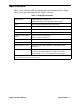
Table 6: Parts List (cont.) Part Number Description 62-0125RK Sensor, combustible gas (hydrocarbon) 65-0601RK Sensor, oxygen 65-2009RK Sensor, hydrogen compensated carbon monoxide 65-2035RK Sensor, hydrogen sulfide 71-0288RK Inert Gas Testing Eagle with Two Pumps Instruction Manual 80-0131RK-10 Probe, 10-inch hydrophobic (standard probe) 80-05XXRK Sample hose. Replace “XX” with length in feet. 5 foot hose is standard.
Appendix B: Methane Elimination For applications where methane is an interfering gas, you can set the Eagle to eliminate most response to methane. The methane elimination switch is a standard feature on the circuit board inside the top of the Eagle’s case. An external switch is available as an option. For this type of detection, the combustible gas channel must be programmed to display HEX or *** (see “Updating Channel Settings” on page 26).
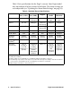
2. Allow 2 minutes for the combustibles sensor to stabilize. 3. Perform the demand zero procedure as described in “Preparing for Calibration” on page 42. Monitoring Combustible Gases Other Than Hexane Use Table 7 to determine the concentration of combustible gases other than hexane. This table is based on the Eagle being in methane elimination mode (methane elimination switch set to HEX ON) and calibrated to hexane. Multiply the display reading by the factor in the appropriate column.
WARNING: The Eagle’s alarms are initiated by the DISPLAY reading not the FACTORED reading. If you are monitoring for toluene as in the above example and the low alarm is set for 10% LEL, the Eagle will initiate a low alarm at 7% LEL toluene (display reading of 10% LEL).
Appendix C: Installing the Data Logger Board Appendix H describes the procedure to install the Eagle’s data logger board. The data logging feature is an optional accessory. NOTE: Although the data logger board may be installed in the field, RKI Instruments, Inc. recommends that you return the Eagle to the factory for data logger board installation. 1. Take the Eagle to a non-hazardous location, and turn the power off. 2.