INSTRUCTION MANUAL MODEL GX-82A PORTABLE THREE GAS DETECTOR RKI Instruments, Inc. 33248 Central Ave.
Model GX-82A Instruction Manual Table of Contents INTRODUCTION DESCRIPTION COMPONENTS AND CONTROLS Case Control Panel Switches Battery Compartment Interface Port Buzzers and Earphone Carrying Case Sensors Combustible Gas Sensor Oxygen Sensor CO, or H2S (toxic gas) Sensor OPERATION Preparation Standard Start-up Normal Operation DISPLAY FUNCTIONS User and Station ID Peak Average Elapsed Time Short-Term Exposure Limit (STL) Time-Weighted Average (TWA) Battery Voltage Date / Time Clear Data Logger Log.
Model GX-82A Instruction Manual MAINTENANCE Batteries Sensor Maintenance Combustibles Sensor O2 Sensor Toxics Sensors Sensor Replacement CO Filter ACCESSORIES Extender Cable Sample-Drawing Pump Manually-Operated Sample-Drawing Aspirator USER OPTIONS Entering Programming Mode General Programming Hints WARRANTY Table of Contents Hayward, California (510) 441-5656 25 25 26 26 27 27 27 28 29 29 29 30 32 32 32 37
Model GX-82A Instruction Manual INTRODUCTION The RKI Model GX-82A is an advanced gas detection instrument, incorporating proven detection hardware and microprocessor controls.
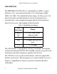
Model GX-82A Instruction Manual DESCRIPTION The RKI Model GX-82A detects combustible gas (LEL), oxygen deficiency (O2), and carbon monoxide (CO) or hydrogen sulfide (H2S). See Table 1 for standard detection ranges for these gases. Gas detection features include distinctive alarms for dangerous gas concentrations, time-weighted averaging and short term exposure limit for toxic gases, and logging of detection data.
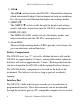
Model GX-82A Instruction Manual COMPONENTS AND CONTROLS Case The GX-82A has a durable plastic case. The sensors are housed in a detachable block at the bottom of the instrument. Control Panel The control panel contains the display, alarm lights, and switches that control the many functions of the GX-82A. The switches are touchpads, to reduce the possibility of accidental activation or damage. See Figure 1. % LEL AIR ▲ PPM % (SHIFT) ▼ ON/OFF /ENTER DISPLAY /(ADJ.) OFF - HOLD 5 SEC Figure 1.
Model GX-82A Instruction Manual 2. AIR/▲ The AIR/▲ switch activates the GX-82A’s Demand Zero function, which automatically adjusts the instrument in fresh-air conditions. It is also used to scroll through the display and settings modes. 3. (SHIFT)/▼ The (SHIFT)/▼ switch scrolls through the display and settings modes, and enters instructions into the GX-82A’s microprocessor. 4. DISPLAY/(ADJ) The DISPLAY/(ADJ) switch activates the display modes, and enters instructions into the GX-82A’s microprocessor. 5.
Model GX-82A Instruction Manual analysis programs. Buzzers and Earphone An electronic buzzer is mounted at the back of the case, behind a felt screen. The buzzer sounds for gas alarms and system malfunctions. A 2.5 mm phone jack at the bottom left rear corner of the case connects to an earphone, for use in high noise environments, and the battery charger. Carrying Case The carrying case has openings for the diffusion grill, buzzer, earphone/charger jack, control panel, and Data Logger interface port.
Model GX-82A Instruction Manual Oxygen Sensor The O2 sensor is an electrochemical cell, which reacts to the oxygen in the atmosphere, producing a current proportional to the oxygen concentration. This current is converted by the GX-82A into an oxygen reading. CO, or H2S (toxic gas) Sensor The toxic gas sensor is an electrochemical cell, which reacts to gas in the atmosphere, producing a current proportional to the concentration of gas.
Model GX-82A Instruction Manual OPERATION Preparation Normally the GX-82A requires little preparation before use. To install the GX-82A Extender Cable, see the ACCESSORIES section. Standard Start-up 1. Press the ON/OFF/ENTER switch once. a.This message shows only when the “Lunchbreak” feature is activated (See USER OPTIONS). Press the AIR/▲ switch to continue Short Term Exposure Limit (STL) and Time-Weighted Average readings from the last use of the GX-82A. Press DISP/ (ADJ.
Model GX-82A Instruction Manual c. This message shows to verify that the data logger circuits are set properly for accurate data collection according to date and time. DATE / TIME MMM DD YY 00:00 Note The display illustrations in this manual show only “H2S.” If your instrument detects CO or another toxic gas, information for that gas will appear in the H2S section of the display. d.These messages show while the GX-82A checks itself for proper operation.
Model GX-82A Instruction Manual operation. HC O2 H2S OK 062796 RKI Instruments, Inc.
Model GX-82A Instruction Manual 2. Verify Operation To easily verify correct operation of the GX-82A, breathe out over the diffusion grill of the instrument. The O2 reading should drop measurably before returning to normal. To verify detection of combustibles use a controlled source of flammable vapor, for example, a bottle of isopropyl alcohol. The audible alarm will sound, the %LEL will blink, and the HC will flash on the display.
Model GX-82A Instruction Manual response. 062796 RKI Instruments, Inc.
Model GX-82A Instruction Manual DISPLAY FUNCTIONS While the GX-82A is in normal operation, press the DISPLAY/(ADJ.) switch to step through the measurement functions. The display will hold for 20 seconds before reverting to normal detection, or until DISPLAY/(ADJ.) is pressed to go to the next screen. User and Station ID This screen appears only when the user ID option is activated. (See USER OPTIONS.) Use this screen to verify user, location, or other programmed information.
Model GX-82A Instruction Manual until a higher level is detected, the data logger is cleared, or the unit is turned off. HC O2 H2S P45 19.5 10.5 Average The Average function shows the average gas concentrations (indicated by “A” at the left side of the display) detected since the last time the GX-82A was turned on or the data logger was cleared. HC O2 H2S A18 20.8 2.5 Elapsed Time The Elapsed Time function shows the time in minutes since the memory was cleared or the instrument was turned on.
Model GX-82A Instruction Manual Time-Weighted Average (TWA) The TWA function shows the average reading for toxic gases during the last 8 hours. If 8 hours has not elapsed since the last time the STEL/TWA was cleared, the average is still calculated over 8 hours, with the missing time assigned a 0 value for readings. (TWA) H2S PPM XX.X Battery Voltage The Battery Voltage function shows the minimum operating voltage and present battery voltage. BATTERY MIN 2.3V BATTERY NOW 3.
Model GX-82A Instruction Manual Clear Data Logger The Clear Data Logger function allows the user to reset the data logger storage to accept a new set of data. Clearing the Data Logger also resets the Peak, Average, Time in Operation, STL, TWA, and Log. Time readings. This function shows three displays. Press AIR/▲ to continue through this function, or DISPLAY/(ADJ.) to skip to the next function. CLEAR DATA LOG. YES:AIR NO:DISP ARE YOU SURE ? YES:AIR NO:DISP CLEARED OK Log. Time The Log.
Model GX-82A Instruction Manual ALARMS Alarm Indications 1. Combustibles (%LEL) If the combustible gas detected exceeds the first level alarm setting (20% LEL for most applications), a pulsed tone will sound, the %LEL LED will blink, and the “HC” on the display will flash. If the combustible gas detected rises above the high alarm setting (50% LEL for most applications), the alarm tone and LED will be continuous. The LEL alarm may be turned off and on by the user; see USER OPTIONS. 2.
Model GX-82A Instruction Manual 5. STEL (toxics only) If the average toxic gas level detected over the last 15 minutes exceeds the STL, an alarm will sound and the message “STL” will show on the display in the field for that gas. The STEL alarm may be turned off and on by the user; see USER OPTIONS. 6. TWA (toxics only) If the average toxic gas level detected over the last 8 hours exceeds the TWA, an alarm will sound and the message “TWA” will show on the display in the field for that gas. 7.
Model GX-82A Instruction Manual Malfunction Alarm and Emergency Operation The GX-82A continuously monitors itself for proper operation. If a malfunction occurs, a single steady “trouble” tone will sound, and one of the following messages will show on the display: 1.
Model GX-82A Instruction Manual Low Battery Alarm When the battery charge drops near the lower limit, the display will show the first screen below, with the “B” flashing. When the charge drops to the limit, the second screen will show, with the “CHANGE BATTERY” flashing, the buzzer will sound continuously, and the GX82A can not be used to monitor gas concentrations: HC O2 H2S CO B 0 20.9 00.0 0 HC O2 H2S CO CHANGE BATTERY 062796 RKI Instruments, Inc.
Model GX-82A Instruction Manual CALIBRATION AND MAINTENANCE The GX-82A’s microprocessor circuits provide advanced calibration and adjustment features, including Demand Zero and Auto Calibration. Note Calibrate the GX-82A when a gas reading drifts below zero or a sensor has been replaced. Calibration Supplies and Equipment For automatic one-source calibration, the RKI Four Gas Cylinder can be used to adjust all sensors with one connection and one operation.
Model GX-82A Instruction Manual 3. Demand Zero Press and hold the AIR/▲ switch on the control panel until a tone sounds. Follow the instructions on the display: DEMAND ZERO HOLD AIR KEY ADJUSTING ZERO HOLD AIR KEY ZERO ADJUSTED RELEASE AIR KEY The instrument will automatically set the LEL and toxic gas circuits to zero and the O2 circuit to 20.9%. Calibration Start-up 1.
Model GX-82A Instruction Manual 2. Enter calibration mode With the instrument on, press and hold the (SHIFT)/▼ switch, then press the DISPLAY/(ADJ.) switch. The display will show: 1.AUTO CAL. 2.SET SPAN The “1” will flash, indicating the active selection. To select Auto Calibration, press ON/OFF/ENTER. (Go to next section, Auto Calibration.) To skip to separate calibration for individual sensors, press the (SHIFT)/▼ switch to scroll down through the calibration menu (Press AIR/▲ to scroll up).
Model GX-82A Instruction Manual Cylinder. AUTO CALIBRATION 50 12.0 25.0 To change the calibration values, press the (SHIFT)/▼ and DISPLAY/(ADJ.). The following screen will appear. SET CAL. 50 LEL Press the AIR/▲ or (SHIFT)/▼ to adjust the LEL value to agree with the concentration on the Four-Gas Cylinder. Press ON/OFF/ ENTER to advance to the SET CAL screen, the repeat the adjustment procedure for O2, H2S and CO. 2.
Model GX-82A Instruction Manual END screen will appear: AUTO CALIBRATION NORMAL END d.After the end screen, the display automatically returns to the first calibration screen. e Turn off the Four-Gas Cylinder and disconnect it from the valve. f. Press (SHIFT)/▼ to scroll through the options to “7.RETURN,” then press ON/OFF/ENTER to return to normal operation.
Model GX-82A Instruction Manual reading stabilizes: HC CAL. 45LEL GAS/ADJ./ENTER 3. If the reading does not correspond to the sample, press the AIR/▲ switch to increase the reading, or the (SHIFT)/▼ switch to decrease the reading. 4. Press ON/OFF/ENTER. The END screen will show: HC CAL. END 5. The display will automatically return to the Calibration Menu. Press (SHIFT) to scroll down to the next desired calibration. 6. Turn off the combustible gas cylinder and disconnect it from the valve. Oxygen Zero 1.
Model GX-82A Instruction Manual 4. The reading should fall to near zero for an oxygen-free sample, or near the level of the low concentration sample. Adjust the reading using the AIR/▲ or (SHIFT)/▼ switches. 5. Press ON/OFF/ENTER to complete the oxygen zero sequence. 6. Turn off the zero oxygen cylinder and disconnect it from the valve.
Model GX-82A Instruction Manual H2S and CO Span 1. Connect a H2S or CO calibration cylinder to the adapter. 2. From the calibration menu, scroll to “4.SET SPAN ,” or “5.SET SPAN .” Press ON/OFF/ENTER to start the selected calibration. 3. Adjust the calibration value following the procedure in Combustibles Span, steps 2 - 6. Note The GX-82A will display up to 99 ppm H2S, but the limit of linear response is 60 ppm, well above acceptable exposure levels.
Model GX-82A Instruction Manual MAINTENANCE Batteries 1. Check the battery voltage periodically by pressing the DISPLAY switch to reach the Battery Voltage function. Replace the batteries before the voltage drops to the operational limit (see OperationAlarms). WARNING TAKE THE GX-82A TO A NON-HAZARDOUS LOCATION BEFORE CHANGING OR CHARGING THE BATTERIES. 2. To replace the batteries, remove the battery compartment cover.
Model GX-82A Instruction Manual 3. Bias Current Discharge The batteries continuously supply a small current to maintain the toxics sensors, even when the instrument is off (see Sensor Maintenance). This current drain is minimal, but will result in a normal discharge of the batteries over a period of several weeks. Note If the batteries are fully discharged before replacement, allow 1/2 hour for the toxic gas circuit to show a normal response.
Model GX-82A Instruction Manual O2 Sensor Replace the O2 sensor when: 1. The O2 circuit cannot be set to 00.0% on an oxygen-free sample. 2. The OXY (O2) display does not show 20.9% immediately after the start-up sequence and after the Demand Zero command. 3. The O2 reading tends to drift with instrument orientation. Toxics Sensors Replace the sensor when: 1. The detection circuit cannot be calibrated correctly. 2.
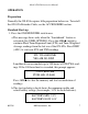
Model GX-82A Instruction Manual 4. To replace individual sensors, press down and turn counter-clockwise, then pull out of block. Figure 2 shows the installation of the CO sensor with filter; do not use the filter with other sensors. Sensor Block CO Sensor Filter (CO only) Rubber Collar (CO only) Figure 2. Sensor Installation 5. Insert a new sensor and turn clockwise. Be sure to use the correct socket for the sensor type; sensors are not interchangeable between sockets. 6. Reinstall the cover. 7.
Model GX-82A Instruction Manual ACCESSORIES Extender Cable The Extender Cable extends the sensor block up to 10 meters from the instrument, allowing confined space and remote monitoring, with all the features of the GX-82A. The Extender cable includes the cable with sensor block plug and socket, and a rubber guard for the sensor cover. 1. Installing Extender Cable Take the GX-82A to a non-hazardous area and turn off. 2. Remove the sensor cover. 3.
Model GX-82A Instruction Manual sensor cover, then slide the pump into place. Make sure the pump housing seats and clips securely. 2. Turn on the pump and the GX-82A and allow it to complete the start-up procedure. 3. Take the instrument into the area to be monitored. Caution Do not place the probe tip in liquid or other materials which could be drawn into the Pump or the GX-82A. 4. Place the probe tip in the desired location to sample the atmosphere. Watch the GX-82A’s display for changes.
Model GX-82A Instruction Manual requirements for portable sample-drawn monitoring. 1. Assemble the probe, hose, bulb, and adapter. Slide the adapter into place over the sensor cover. 2. Turn on the GX-82A and allow it to complete the start-up procedure. 3. Take the instrument into the area to be monitored. Caution Do not place the probe tip in liquid or other materials which could be drawn into the Aspirator accessory or the GX-82A. 4.
Model GX-82A Instruction Manual USER OPTIONS The advanced microprocessor program in the GX-82A allows the user to select and adjust many of the detection and data logging features. The GX-82A is pre-set to suit most applications; follow these instructions only if required. Entering Programming Mode 1. Take the GX-82A to a non-hazardous location—the instrument does not detect gas during programming operations. 2. Turn the GX-82A off. 3. Hold down the AIR and (SHIFT) switches, then press ON.
Model GX-82A Instruction Manual SET DEF. NVRAM 1. “DEF. SET ALL” The first option allows the user to reset all values for non-volatile RAM; all options are returned to default values. 2. “DEF. SET ALARM” The second option resets only the alarm levels to default values. 3. “DEF. SET O2 ZERO” The third option resets the O2 zero to default value. COMBINE GAS Sets the display and circuitry for types of gases to be detected; there are five possible combinations.
Model GX-82A Instruction Manual 3. “SET ALARM or ” Prompts changes for LOW, TWA, STL, and CLG (ceiling) alarms for H2S or CO. SET SERIAL No. Sets the serial number for use by the Data Logger. 1. At the “SERIAL No.” screen, the first character (left end) will flash. Press AIR or SHIFT to scroll through 0 - 9, A - Z to select the desired character. 2. Press ON/OFF/ENTER to enter that value and move to the next character. 3. Repeat steps 1. and 2.
Model GX-82A Instruction Manual LATCHING ALARM Toggles the instrument alarm logic between self-resetting (default) and latching alarms. Note In the event of an alarm, the latching alarms option requires the user to press DISPLAY/(ADJ.) to reset the alarms, even after the gas concentration has dropped below the alarm level. SET LUNCH Toggles the Lunchbreak feature on and off. With Lunchbreak off (default), the STL TWA RESUME screen does not show at start-up. SET ID Toggles the ID INPUT option on and off.
Model GX-82A Instruction Manual AUTO CAL. The procedure is the same as described in Calibration and Maintenance, Auto Calibration. DISPLAY VOL. This feature is for factory use only. START Press ON/OFF/ENTER to begin the instrument’s normal start-up sequence. 062796 RKI Instruments, Inc.
Model GX-82A Instruction Manual WARRANTY RKI Instruments, Inc. warranties gas alarm equipment manufactured by Riken Keiki Co., Ltd., and sold by us to be free from defects in materials and workmanship for a period of one year from date of shipment from RKI Instruments, Inc. Any parts found defective within that period will be repaired or replaced, at our option, free of charge.