H4E-0050 Portable Gas Monitor GX-8000 User Maintenance Manual (H4-0050) Need of Maintenance and Servicing This gas monitor must be maintained in a normal state at all times to prevent accidents due to gas leaks. Daily and regular maintenance is required to keep the gas monitor in a normal state. Neglecting maintenance will result in failures and false alarms. The specified maintenance procedures must be performed for the sake of maintenance of a normal state.
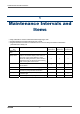
1 Maintenance Intervals and Items 1 Maintenance Intervals and Items • Daily maintenance: Perform maintenance before beginning to work. • Monthly maintenance: Perform alarm test once a month. • Regular maintenance: Perform a maintenance once or more for every six months to maintain the performance as a safety unit. Maintenance item Daily maintenance Monthly maintenance Regular maintenance Check that the battery level is sufficient. { { { Make the gas monitor draw in fresh air.
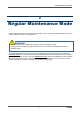
2 Regular Maintenance Mode 2 Regular Maintenance Mode Regular maintenance mode is an operation (adjustment) mode in which span adjustment and setup such as change of alarm setpoints can be performed. WARNING After the adjustment is completed, do not forget to return to the detection mode. (If the gas monitor remains in the regular maintenance mode, it does not automatically return to the detection mode.) The regular maintenance mode comes in two types: Calibration and maintenance modes.
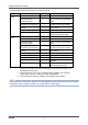
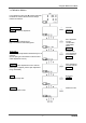
2 Regular Maintenance Mode The regular maintenance mode has the menus shown below. Mode Calibration mode Item Fresh air adjustment Zero adjustment for high-concentration combustible gases Simultaneous span adjustment for all channels Span adjustment for each channel Bump test Exit calibration mode LCD display AIR CAL VOLZ.CAL Details Perform the fresh air adjustment. Perform the zero adjustment for high-concentration combustible gases. AUTO CAL Perform the span adjustment simultaneously for all channels.
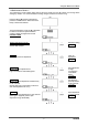
2 Regular Maintenance Mode <> In the detection mode, keep T pressed and press the DISPLAY switch. When the buzzer beeps, release the switches. Calibration mode AIR CAL Perform the fresh air adjustment. Fresh air adjustment => P16 VOLZ.CAL Perform the zero adjustment for high-concentration combustible gases. Zero adjustment for highconcentration combustible gases => P20 AUTO CAL Perform the span adjustment simultaneously for all channels.
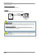
2 Regular Maintenance Mode Required equipment/material • Bump test gas (collected in a gas sampling bag) Connection Connect the equipment as shown below to perform the bump test. Gas sampling probe (with a tube) Gas sampling bag GAS IN GAS OUT (Open) GX-8000 main unit WARNING About the bump test gas The bump test gas is a hazardous gas (toxic, oxygen deficient, etc.). Handle the gas and related jigs and tools with due care (e.g.
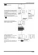
2 Regular Maintenance Mode BUMP Press the ENTER switch. The bump test gas concentration is displayed. The concentration of the prepared test gas must be consistent with the displayed test gas concentration. To change the test gas concentration value, change the value in span adjustment menu. The test gas concentration is set to the same value as the span gas concentration. Simultaneous span adjustment for all channels => P18 NOTE Supply the test gas.
2 Regular Maintenance Mode (2) Continue supplying the test gas. Continue supplying the gas. The result is not displayed, and the span adjustment is automatically started. CAL and APPLY are displayed alternately, and the countdown is started. The span adjustment is started in about 30 seconds, and the result is displayed.
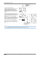
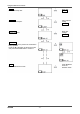
2 Regular Maintenance Mode <> The maintenance mode includes setting menus which are usually not used. Be careful not to change these settings by mistake. It is recommended that setting changes should be recorded in a log. Keep the S and T switches pressed and press the POWER switch. When the buzzer beeps, release the switches. The input field blinks. Press the S or T switch to select a number and press ENTER to confirm it. Enter four digits from the left.
2 Regular Maintenance Mode BUMP Perform the bump test. Bump test => P6 ALARM-P Set the alarm setpoint. Alarm setpoint setting => P12 BUMP-SET Set the bump test. Bump test settings => P13 BEEP SET Set whether or not to perform the confirmation beep operation. Press the S or T switch to select ON or OFF and press the ENTER switch to confirm it. Press ENTER to enter the detection mode. START Exit the maintenance mode.
2 Regular Maintenance Mode <> Set the date/time. DATE Press the ENTER switch. The input field blinks. Enter the year, month, day, hour, and minute in this order. Press the S or T switch to adjust the date and time and press the ENTER switch to enter it. (The figure on the right shows an example of input for 2011/01/07 19:32.) As soon as the last part (minute) is entered, the date/time setting is confirmed.
2 Regular Maintenance Mode Set the alarm setpoint. ALARM-P Press the ENTER switch. The alarm setpoint setting selection menu is displayed. Press the S or T switch to display a target gas for which the alarm setpoint should be set. Every time the S or T switch is pressed, the target gas is changed (in the order of Combustible, O2, H2S, CO, and ESCAPE).
2 Regular Maintenance Mode Check and set the setting items related to the bump test. BUMP-SET Press the ENTER switch. Press the S or T switch to display a target setting item to be checked or set. The test time is displayed. Press the ENTER switch. The numeric display blinks, prompting for input. Press the S or T switch to enter introduction time. Press the ENTER switch to confirm it. The figure on the right shows an example of 30 seconds.
3 Span Adjustment 3-1. Preparation for span adjustment 3 Span Adjustment 3-1. Preparation for span adjustment Required equipment/material • Zero adjustment gas for high-concentration combustible gases (collected in a gas sampling bag) • Span adjustment gas (collected in a gas sampling bag) • Stopwatch Connection Connect the equipment as shown below to perform the span adjustment.
3-1. Preparation for span adjustment 3 Span Adjustment Perform adjustment using the procedure shown below. (1) Fresh air adjustment (AIR CAL) *1 Warm up the gas monitor for 60 minutes or longer before performing the fresh air adjustment to ensure more accurate adjustment. (2) Span adjustment (AUTO CAL or ONE CAL) *1 The gases may be introduced in random order. • Combustible gas (%LEL) • O2 gas *1 • CO gas • H2S gas (3) Zero adjustment for high-concentration combustible gases (VOL Z.
3 Span Adjustment 3-2. Fresh air adjustment 3-2. Fresh air adjustment WARNING When the fresh air adjustment is performed in the atmosphere, check the atmosphere for freshness before beginning the adjustment. If other gases exist, the adjustment cannot be performed properly, thus leading to dangers when the gas leaks.
3-2. Fresh air adjustment 3 Span Adjustment AIR CAL Press the ENTER switch. The current concentration readings of the gases are displayed. Press the AIR switch when they are stabilized. When the AIR switch is pressed, HOLD AIR is displayed. Keep pressing the switch until RELEASE is displayed. Release the AIR switch. * Only on TYPE-A and TYPE-E, a 30-second countdown is started. No countdown is started on other types.
3 Span Adjustment 3-3. Span adjustment 3-3. Span adjustment AUTO CAL Press the ENTER switch. The span gas concentration is displayed. It needs to be consistent with the concentration of the prepared span gas. To change the value, press the T and DISPLAY switches simultaneously. The span gas concentration setting menu is displayed.
3-3. Span adjustment 3 Span Adjustment ONE CAL Press the ENTER switch. The span adjustment selection menu is displayed. Press the S or T switch to display a target gas for which the span adjustment should be performed. Every time the S or T switch is pressed, the target gas is changed (in the order of Combustible, O2, H2S, CO, and ESCAPE).
3 Span Adjustment 3-3. Span adjustment (Only TYPE-A, E) VOL Z.CAL Press the ENTER switch. The VOL Z.CAL display blinks. Until the combustible gas range switches to VOL%, the combustible gas concentration is displayed as ---. The current concentration readings of the combustible gas and oxygen are displayed (prompting for supply). Prepare and supply the zero gas. Supply the zero gas.
4 Replacement of Consumable Parts 4 Replacement of Consumable Parts (1) Loosen the four screws on the sensor cover and remove the sensor cover. (2) Remove the sensor rubber seal. Take care not to damage the sensor rubber seal and the seal surface inside the sensor cover that comes into contact with the rubber seal. Sensor cover Sensor rubber seal Peel it off if it sticks to the sensor cover. Captive screws (four) (3) Replace the sensor.
4 Replacement of Consumable Parts (4) Using an opposite procedure to the above, install the sensor rubber seal and fix the sensor cover. Screw tightening torque: 5 to 5.5 kgf・cm (49 to 54 N・cm) Sensor rubber seal Install the rubber seal so that the concave part covers the sensor. Install the sensor cover horizontally so as not to warp the sensor rubber seal.
Warranty Policy RIKEN KEIKI CO., LTD., warrants gas alarm equipment sold by us to be free from defects in materials, workmanship, and performance for a period of one year from date of shipment from RIKEN KEIKI CO., LTD., Inc. Any parts found defective within that period will be repaired or replaced, at our option, free of charge.