
User Manual


32 • Write Commands
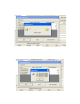
If any of the channels failed the zero adjustment, the
message in the Adjustment Window for that channel will
indica te that t he zer o adjustm ent failed. Click OK to return to
the Calibration Window. See the GX-2009 Operator’s
Manual for troubleshooting suggestions.
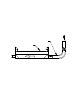
7. Use the calibration kit sample tubing to connect the
calibratio n adapter plate to the regulator. Att ach the tubing t o
the adapter plat e on the inlet side as shown below in
Figure 26.
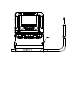
8. Confirm that the regulator on/off knob is turned all the way
clockwise (closed) and screw the calibration gas cylinder
onto the r egulator.
9. Hold the GX-2009 in pl ace with one hand while pushing the
adapter plate onto the GX-2009’s sensor face with the other
to avoid moving the GX-2009 excessively and losing the
connection to the comp uter. Make sure the adapter plate is
oriented as shown in Figure 27 below with the sensor name s
on the adapter plate matching up with the sensor names on
the instrument.
O
2
CO
Flow
To Fixed Flow
Regulator
Cali bration Tubing
T
Tubin g
Adapte r Pl at e
%LEL
H
2
S
Figure 26: Calibration Kit Assembly