GX-2009 User Setup Program Operator’s Manual Part Number: 71-0162RK Revision: E Released: 9/24/13 www.rkiinstruments.
Warranty RKI Instruments, Inc. warrants gas alarm equipment sold by us to be free from defects in materials and workmanship, and performance for a period of one year from date of shipment from RKI Instruments, Inc. Any parts found defective within that period will be repaired or replaced, at our option, free of charge.
Table of Contents Warranty . . . . . . . . . . . . . . . . . . . . . . . . . . . . . . . . . . . . . . . . . . . . . . . . . . 2 Table of Contents . . . . . . . . . . . . . . . . . . . . . . . . . . . . . . . . . . . . . . . . . . . 3 Introduction . . . . . . . . . . . . . . . . . . . . . . . . . . . . . . . . . . . . . . . . . . . . . . . 4 System Requirements . . . . . . . . . . . . . . . . . . . . . . . . . . . . . . . . . . . . . . . 5 Installing the GX-2009 User Setup Program . . . . . . . . . . . . .
Introduction NOTE: The bump test function in Calibration Mode is included in instruments with firmware version 03955 or later installed. See page 48 for a description of the bump test function. GX-2009 instruments shipped after May 2011 include the bump test function. Instruments that have a serial number starting with 04516 or later shipped from the factory with the bump test function available.
• install the downloading cable (if needed) • connect to the GX-2009 with the program • change parameters in the GX-2009 • save parameter configuration files that can be opened and viewed in a spread sheet program • save parameter configuration files that can be uploaded to an instrument to change its parameter settings • upload parameter configuration files to an instrument to change its parameter settings Before you get started, be sure to review system requirements in the next section.
higher. • Memory: 32 MB RAM minimum • Available Hard Disk Space: 32 MB minimum • CD-ROM Drive • Infrared port or USB port and a USB/IrDA adapter cable Installing the GX-2009 User Setup Program 1. Launch Windows®. 2. Exit from all applications and open windows. 3. Insert the GX-2009 User Setup Program Installation CD in your computer’s CD-ROM drive. NOTE: If you have a GX-2009 Product CD instead of a GX2009 User Setup Program Installation CD, insert the Product CD and navigate to the User Setup folder.
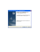
4. After a few seconds, a screen appears indicating that the InstallShield Wizard is preparing to install the User Setup Program, then the GX-2009 Configuration for User InstallShield Wizard window appears to guide you through installation. Figure 1: GX-2009 User Setup Installation Program 5. Follow the on-screen instructions in the Installation Wizard Window to install the program. 6.
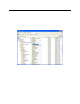
Installing a Newer Version of the GX-2009 User Setup Program If you are installing a more recent version of the GX-2009 User Setup Program software, you must follow these instructions. 1. Unistall the currently installed version of the software. 2. Delete the GX-2009 User Config folder from the Program Files folder of the hard drive. Figure 2: GX-2009 User Config Folder in Program Files 3. Use the product CD to install the new version of the User Setup program. 4.
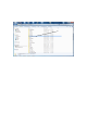
5. If you are installing a new version of the User Setup Program on a Windows® Vista or a Windows® 7 computer, a “Compatibility Files” button may appear in the windows explorer toolbar when you navigate to the GX-2009 User Config Program Files folder.
Click this button Figure 4: Compatibility Files Button If it does, click the Compatibility Files button. It will direct you to another folder that contains any compatibility files for the directory.
Delete any files that appear in this new folder. 6. Run the User Setup program and ensure that it is operating correctly. IrDA Downloading Cable The GX-2009 communicates with a computer via an on-board infrared communication port that complies with IrDA protocol standards. NOTE: If your computer has a built-in infrared port, you do not need an adapter cable to download data.
Hardware Wizard to install the cable drivers. Windows® Wireless Link Operation Note When using an IrDA adapter cable and the GX-2009 User Setup Program on a Windows® computer, it is necessary to make a special setting in the Wireless Link Configuration window for proper communication between the GX-2009 and the GX-2009 User Setup Program. This must be done before attempting to use the program. Follow these steps to make this setting: 1. Click Start on the Windows® Icon Tray. 2.
Figure 6: Image Transfer Tab 6. Click OK. 7. Close the Control Panel window.
Launching the Program 1. Click Start in the Windows® Icon Tray, then select Programs, then select GX-2009 Configuration for User. Your operating system may also have a shortcut installed in the Start menu. 2. The program will launch and the Password Window will appear. Figure 7: The Main Window 3. The password to enter the User Setup Program is “1994”. Type in the password and click OK to proceed. 4. The Main Window will appear.
5. For convenience, make a shortcut of the GX-2009 User Setup Program and place it on the Windows® desktop. See your Windows® documentation for information about making shortcuts. Connecting a GX-2009 to the User Setup Program Follow these steps to connect a GX-2009 to the User Setup Program: 1. Launch the GX-2009 User Setup Program as described in “Launching the Program” on page 14. The Main Window displays. Figure 9: The Main Window 2.
If your computer does not have a built in infrared port, place the GX-2009 within an inch or two of the infrared port on the IrDA adapter cable as shown in Figure 10 below, aligning the infrared port on the top of the GX-2009 with the infrared port on the cable. GX-2009 To Computer USB Port Sensor Diffusion Port, 4X Cable's Infrared Port Infrared Port Figure 10: Aligning the GX-2009 with the Cable Infrared Port 3.
indicate that a wireless connection is in effect. PC TRANSMIT 4. There are two exceptions to the sequence described in step 3 above. See “Detail Settings” on page 44 for a description of the Cal Limit Display and Cal Limit Check parameters. • When Cal Limit Display is set to On and Cal.
5. There are two additional exceptions to the sequence described in step 3 above if the unit includes the bump test function and if Bump Limit Display is set to On. See “Detail Settings” on page 44 for a description of the Bump Limit Display and Bump Limit Check parameters.
configuration to a file and changing the instruments parameter configuration. The three basic command sets for performing these operations are the Read Commands, Write Commands, and Setting Commands. These command sets are described in the sections that follow.
When the User Setup Program is first launched, the Read Command control buttons are blanked out. They become active when an instrument is connected to the program. Figure 13: Read Commands, Active Instrument Information Use Instrument Information to load a connected instrument’s parameter configuration into the User Setup Program so it can be updated if desired.
downloading information from the instrument. Figure 14: Instrument Information Downloading 4. The instrument’s parameter configuration is now loaded in the User Setup Program and parameters are available for updating in the GX-2009 Status area of the Main Window and in the Factory Settings Window. The Factory Settings Window is accessed using the Detail Settings command button in Setting Commands. See “Detail Settings” on page 44 for a description of Detail Settings. 5.
box. If the box is selected, the corresponding channel will be enabled when the change is uploaded to a GX-2009. If the box is deselected, the corresponding channel will be disabled when the change is uploaded. 6. Once you have made the desired parameter edits, click Update in the Write Commands.The following window appears prompting you to confirm that you want to make the update. Figure 15: Update Window 7. Click Yes to proceed. The program will indicate that it is uploading information to the GX-2009.
8. When the uploading is complete, the program will indicate that it is done. Figure 17: Upload Complete Window 9. Click OK. The program will return to the Main Window. Information Get & Save Use Information Get & Save to load a connected instrument’s parameter configuration into the User Setup Program and edit parameters, just like Instrument Information. In addition, you can save an instrument’s parameter configuration and most recent calibration information to a .
3. Click in the Filename Suffix at Save field and enter a file name suffix. When you use Instrument Get & Save, the program saves a connected instrument’s parameter configuration and most recent calibration information to a .csv file with the file name “GX2009_Setting[suffix].csv”. You can add the instrument’s parameter configuration to an existing file or create a new file by using the Filename Suffix at Save field. The entered suffix is added to the end of the filename, before the file extension.
5. The program will retrieve the instrument’s parameter configuration and most recent calibration information then add them to an existing .csv file or save a new .csv file with the instrument’s parameter configuration and most recent calibration information as described in step 3 above. 6. Use a spreadsheet program such as Microsoft Excel to open and view the saved .csv files. 7.
Write Commands Use the Write Commands to upload parameter changes and calibration adjustments to a connected instrument.The three Write Commands are Update, Date/Time Set, and Calibration. Figure 19: Write Commands, Blanked Out When the User Setup program is first launched, the Write Command control buttons are blanked out. They become active when an instrument is connected to the program.
sections in this manual. Date/Time Set Use Date/Time Set to update the date and time in a connected instrument to match the computer’s date and time. Follow these steps to update an instrument’s date and time: 1. Launch the GX-2009 User Setup Program as described in “Launching the Program” on page 14. 2. Connect the GX-2009 to the User Setup Program as described in “Connecting a GX-2009 to the User Setup Program” on page 15.
window. Figure 22: Upload Complete Window 5. Click OK. The program will return to the Main Window. Calibration Use Calibration to calibrate an instrument by adjusting the instrument’s zero (fresh air) and span settings. Performing a span adjustment requires the use of a calibration kit. The procedure below describes a span adjustment of all four channels using a calibration kit that includes a 4-gas calibration cylinder, a 0.
Follow these steps to calibrate an instrument: 1. Confirm that the area where you will perform the calibration is a fresh air environment. 2. Launch the GX-2009 User Setup Program as described in “Launching the Program” on page 14. 3. Connect the GX-2009 to the User Setup Program as described in “Connecting a GX-2009 to the User Setup Program” on page 15. NOTE: It is not necessary to use Instrument Information or Instrument Get & Save in order to perform a calibration.
There are four column headings and three control buttons in the GX-2009 Calibration Window. • Gas The Gas column shows the four detection channels, the target gas for each channel, and the detection range full scale value for each channel. • Select The Select column has a selection box for each channel that allows you to select or deselect a channel for zero and span adjustments. • Auto Cal. The Auto Cal. column displays the auto calibration values for each channel.
5. Click Zero. The program will take a few seconds to adjust the instrument’s zero (fresh air) settings. The Adjusting Zero Window will appear during this period. Figure 24: Adjusting Zero Window 6. When the zero adjustment is complete, the Adjustment Complete Window will indicate that the adjustment was completed for each channel if it was successful. Click OK to return to the Calibration window.
If any of the channels failed the zero adjustment, the message in the Adjustment Window for that channel will indicate that the zero adjustment failed. Click OK to return to the Calibration Window. See the GX-2009 Operator’s Manual for troubleshooting suggestions. 7. Use the calibration kit sample tubing to connect the calibration adapter plate to the regulator. Attach the tubing to the adapter plate on the inlet side as shown below in Figure 26.
To Fixed Flow Regulator RKI GX-2009 POWER MODE AIR H 2S CO %LEL O2 Adapter Plate O2 %LEL CO H2S Flow Figure 27: Installing the Adapter Plate, Auto Cal 10.Turn the regulator on/off knob counterclockwise to open it. Calibration gas will begin to flow. 11.Allow the gas to flow for two minutes. 12.Click Span. The program will take a few seconds to adjust the instrument’s span settings. The Adjusting Span Window will appear during this period.
Figure 28: Adjusting Span Window 13.When the span adjustment is complete, the Adjustment Complete Window will indicate that the adjustment was completed for each channel if it was successful. Click OK to return to the Calibration Window.
message in the Adjustment Window for that channel will indicate that the span adjustment failed. Click OK to return to the Calibration Window. See the GX-2009 Operator’s Manual for trouble shooting suggestions. 14.Turn the regulator on/off knob clockwise to close it. 15.Hold the GX-2009 in place with one hand while removing the adapter plate from the GX-2009’s sensor face with the other to avoid moving the GX-2009 excessively and losing the connection to the computer 16.
Setting Commands Use the Setting Commands to turn off an instrument, load a selected parameter configuration file to an instrument, save a parameter configuration file based on an instrument’s settings, change various instrument parameter settings that can be uploaded to an instrument, or exit the program. The five Setting Commands are Power Off, Load local file, Store local file, Detail Settings, and Exit.
that you want to turn off the instrument. Figure 31: Setting Commands 3. Click Yes. The program will take several seconds to turn off the instrument. The Connect Light in the Status area will turn gray indicating no connection to an instrument and the parameter fields in the GX-2009 Status area will become empty except for the PC Date/Time and the Interval Trend Time fields.
When you upload a parameter configuration file to an instrument, you are uploading instrument parameters such as alarm points, alarm pattern, calibration frequency, etc. Uploading a parameter configuration file to an instrument will not change the instrument identification parameters, serial number, user ID, and station ID, if the file was created from a different instrument. Follow these steps to load a parameter configuration file to the program and upload it to an instrument: 1.
3. Click Load local file. The Open Window will appear allowing you to navigate to a file location and select a file to load. Figure 32: Open Window 4. Use the Open Window to navigate to the location of the file you wish to load. 5. Select the file you wish to load and click Open. The program will load the parameter configuration file and all of the parameter fields that can be uploaded from a parameter configuration file will be populated by the file’s settings.
6. Click Update in the Write Commands. The Update Window will appear prompting you to confirm that you want to update the instrument. Figure 33: Update Window 7. Click Yes. The program will indicate that uploading is taking place with the Upload Window.
8. When the uploading is complete, the program will indicate that it is done. Figure 35: Upload Complete Window 9. Click OK. The program will return to the Main Window. The instrument’s parameters have now been updated based on the loaded parameter configuration file. Store Local File Use Store Local File to save a parameter configuration file based on an instrument’s parameter settings.
in “Load Local File” on page 37. A parameter configuration file containing RKI standard settings can be found on the GX-2009 Product CD and can be used after a default reset if a parameter configuration file was not saved. Once the RKI standard setting file is loaded, the settings can be changed to match the original configuration of the GX-2009. The parameter configuration files that are created have a .seq file extension. These files can only be used by the User Setup Program.
3. With the Read Command Buttons now active, click Instrument Information to retrieve the instrument’s parameter configuration. The program indicates that it is downloading information from the instrument. Figure 36: Instrument Information Downloading 4. The instrument’s parameter configuration is now loaded in the User Setup Program. 5. Click Store local file. The Save As Window will appear allowing you to navigate to a file location and save a file to the selected location.
Figure 37: Save As Window 6. Use the Save As Window to navigate to the location where you want to save the file. 7. Type in a file name in the file name field. If you forget to include the .seq file extension, the program will automatically include it when it saves the file. 8. Click Save. The program will save the file and return to the Main Window. Detail Settings Use Detail Settings to set a variety of instrument parameters so that you can upload them to an instrument.
is received as new if the factory settings for them are not how you want them. The Factory Settings Window that is accessible with the Detail Settings button is shown below with the factory settings for each of these instrument parameters. If any of these settings is not set as you want, see the instructions in “Updating an Instrument’s Detail Settings” on page 50 to change them. The Detail Settings are described below.
Logger Overwrite With Logger Over Write set to On (factory setting), the GX-2009 writes over the oldest data with new data when the data logger memory is full. With Logger Over Write set to Off, the GX-2009 stops saving data to the data logger when the data logger memory is full to avoid overwriting old data. Calibration Time Limit This setting defines the amount of time between calibrations. The minimum setting is 1 day and the maximum setting is 365 days. The factory setting is 90 days. Cal.
instructions to calibrate an instrument using Calibration Mode or User Setup Mode. With Cal. Limit Check set to None, no confirmation during startup or calibration is required to use the GX-2009 if it is past due for calibration. LCD Backlight Time This setting indicates the length of time the LCD backlight is on after when you press any button. The minimum setting is 0 seconds. The maximum setting is 60 seconds. The factory setting is 30 seconds.
User Password User Password allows you to define the password that allows you to enter Calibration Mode or User Setup Mode if Enable User Password is set to On. Bump Test Function This item turns the bump test function on or off (factory setting). With Bump Test Function set to On, the BUMP item will appear in the Calibration Mode menu. This menu item allows you to bump test the GX-2009. With Bump Test Function set to Off (factory setting), the BUMP item will not appear in the Calibration Mode menu.
Bump Test Limit Check This item defines what indication is given during start up when bump testing is due and Bump Test Limit Display is set to On. With Bump Test Limit Check set to Confirm to use (factory setting), the GX-2009 will give an indication at start up if bump testing is due and require the user to press and release the POWER MODE button to continue.
Calibration After Bump Test Failed Calibration automatically begins after a failed bump test if set to On (factory setting). Updating an Instrument’s Detail Settings Follow these steps to update an instrument’s detail settings: 1. Launch the GX-2009 User Setup Program as described in “Launching the Program” on page 14. 2. Connect the GX-2009 to the User Setup Program as described in “Connecting a GX-2009 to the User Setup Program” on page 15. 3.
5. Click Detail Settings. The GX-2009 Factory Setting Window will appear. Figure 40: GX-2009 Factory Settings Window 6. Select the parameter or parameters that you want to change and update them. If you click a parameter setting field and there are multiple choices for that parameter setting, a drop down menu will appear so that you can choose the setting you want. If a parameter setting is a numerical value, you can click in the field for that parameter setting and enter the desired value. 7.
8. Click Update in the Write Commands.The following window appears prompting you to confirm that you want to make the update. Figure 41: Update Window 9. Click Yes to proceed. The program will indicate that it is uploading information to the GX-2009.
10.When the uploading is complete, the program will indicate that it is done. Figure 43: Upload Complete Window 11.Click OK. The program will return to the Main Window. Exit Click Exit to shut down the User Setup Program. If an instrument is connected to the program, make sure to turn off the instrument before shutting down the program to avoid leaving the instrument on in PC Mode and draining the battery.
Table 1: Spare Parts List Part Number Description 81-GX01HSCO One 58 ltr. aluminum cylinder, regulator, calibration plate, case & tubing 81-GX01HSCO-LV One 34 ltr. aluminum cylinder, regulator, calibration plate, case & tubing 81-GX01CO One 103 ltr. cylinder, regulator, calibration plate, case & tubing 81-GX01CO-LV One 34 ltr.