GX-2009 Portable Gas Monitor Operator’s Manual Part Number: 71-0158RK Revision: H Released: 6/18/14 www.rkiinstruments.
WARNING Read and understand this instruction manual before operating instrument. Improper use of the gas monitor could result in bodily harm or death. Periodic calibration and maintenance of the gas monitor is essential for proper operation and correct readings. Please calibrate and maintain this instrument regularly! Frequency of calibration depends upon the type of use you have and the sensor types.
Warranty RKI Instruments, Inc. warrants the GX-2009 sold by us to be free from defects in materials, workmanship, and performance for a period of two years from the date of shipment from RKI Instruments, Inc. This includes the instrument and the original sensors. Replacement parts are warranted for 1 year from the date of their shipment from RKI Instruments, Inc. Any parts found defective within their warranty period will be repaired or replaced, at our option, free of charge.
Table of Contents Introduction . . . . . . . . . . . . . . . . . . . . . . . . . . . . . . . . . . . . . . . . . . . . . . . . . . . . . . . . . . 1 Specifications. . . . . . . . . . . . . . . . . . . . . . . . . . . . . . . . . . . . . . . . . . . . . . . . . . . . . . . . . 2 Description . . . . . . . . . . . . . . . . . . . . . . . . . . . . . . . . . . . . . . . . . . . . . . . . . . . . . . . . . . . 3 Case . . . . . . . . . . . . . . . . . . . . . . . . . . . . . . . . . . . . . . . . . . . . . . . .
User Setup Mode . . . . . . . . . . . . . . . . . . . . . . . . . . . . . . . . . . . . . . . . . . . . . . . . . . . . . 47 Using User Setup Mode . . . . . . . . . . . . . . . . . . . . . . . . . . . . . . . . . . . . . . . . . . . 47 Setting the Date & Time . . . . . . . . . . . . . . . . . . . . . . . . . . . . . . . . . . . . . . . . . . . 49 Performing a Fresh Air Adjustment . . . . . . . . . . . . . . . . . . . . . . . . . . . . . . . . . . . 49 Performing a Span Adjustment in AUTO CAL. . . . . . . .
Introduction Using an advanced detection system consisting of four gas sensors, the GX-2009 personal four-gas monitor detects the presence of combustible gas, oxygen (O2), carbon monoxide (CO), and hydrogen sulfide (H2S) simultaneously.
Specifications Table 1: Model GX-2009 Specifications Target Gas Combustibles, Methane (CH4) calibration standard* Oxygen (O2) Hydrogen Sulfide (H2S) Carbon Monoxide (CO) Range (Increment) 0-100% LEL (1% LEL) 0-40.0 vol% (0.1 vol%) 0-100.0 ppm (0.5 ppm) 0-500 ppm (1 ppm) Detection Method Diffusion Response Time T90 Within 30 Seconds Accuracy ± 5% of reading or ± 2% LEL (whichever is greater) Display ± 0.
Table 1: Model GX-2009 Specifications Continuous Operating Hours Up to 20 Hours (Non Alarm Operation After Full Charge) Charge Time 3 hours for a full charge Case High-impact Plastic, Dust and Water Resistant to IP-67 Required Accessories AC or DC Charging Station, AC Charging Station Available For From 1 to 5 Instruments Other Accessories • IrDA/USB cable for downloading data to computer • GX-2009 Data Logger Management Program (Windows® 2000, XP, Vista) • • • • Dimensions and Weight GX-2009 Set
Description This section describes the GX-2009’s components and the charging station. These components include the GX-2009’s case, alligator and belt clips, sensor retainer, sensor retainer gasket, sensor cover retainer, scrubber filters, sensor cover, sensors, LCD, control buttons, printed circuit boards, alarm LED arrays, buzzer, vibrator, batteries, and charging station.
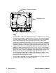
Battery Charging Contacts Threaded Inserts Figure 2: GX-2009 Rear View Case The GX-2009’s sturdy, high-impact plastic case is suitable for use in many environmental conditions, indoors and out. The unit is dust proof and water resistant. Rubber overmolded surfaces on much of the case help protect it from impact damage and aid in holding the instrument in your hand. A clear plastic window through which the LCD can be viewed is located on the front of the case.
Alligator & Belt Clips The GX-2009 is available with two types of clips, the standard alligator clip and the optional belt clip. Both are illustrated in Figure 3. Alligator Clip Belt Clip Figure 3: Alligator and Belt Clips The alligator clip can be used to attach the GX-2009 to clothing or a belt. Teeth in the alligator clip’s jaws prevent the unit from slipping off. The alligator clip can be rotated to change how the instrument is oriented when worn.
sensor will respond if exposed to H2S and certain hydrocarbon gasses. The charcoal filter scrubs these gasses out of the gas sampled to avoid false CO readings. The H2S absorbing material added to the charcoal filter extends it’s H2S absorbing life. If false CO readings are noticed, especially high readings in the presence of H2S, change the charcoal filter disk.
Oxygen (O2) Sensor The O2 sensor is a galvanic type sensor. A membrane covers the cell and allows gas to diffuse into the cell at a rate proportional to the partial pressure of oxygen. The oxygen reacts in the cell and produces a voltage proportional to the concentration of oxygen. The voltage is measured by the GX-2009’s circuitry, converted to a measurement of gas concentration, and displayed on the LCD.
Table 2: GX-2009 Control Buttons Button Function AIR • Turns the LCD back light on. • Performs a fresh air adjustment • Enters Calibration Mode with the MODE POWER button. • Enters User Setup Mode with the MODE POWER button.
charge remaining in the batteries. See “Recharging the GX-2009’s NiMH Batteries” on page 55 for instructions to recharge the batteries and “Replacing the GX-2009’s NiMH Batteries” on page 59 for instructions to replace the batteries. Charging Station The GX-2009’s NiMH batteries are charged with the GX-2009 Charging Station. There are two types of charging stations available, the standard AC powered charging station and the optional vehicle plug DC powered charging station.
Charging stations for more than one instrument include additional chargers that are attached to each other. The same AC adapter can power up to a maximum of 5 charging bases. The two instrument charging station is shown in Figure 5, and the five instrument station is shown in Figure 6.
DC Powered Charging Station An optional DC powered single instrument charging station is available with a vehicle plug 12 VDC adapter. The DC adapter for the charging station can only provide enough power to charge one instrument at a time, so the DC powered charging station is only available as a single instrument charging station. It uses the same charging base as the AC powered charging station.
Start Up This section explains how to start up the GX-2009 and get it ready for operation. Start-up Procedure 1. Press and briefly hold down the POWER MODE button. The backlight will turn on and all the display segments will turn on. Release the button when you hear a beep. 2. The vibrator vibrates and the alarm lights flash momentarily. 3. If Cal. Limit Display is turned on, the screen that appears next depends on how Cal. Limit Check is set.
• If calibration is not due or Cal. Limit Check is set to None, then the following screen appears for a few seconds indicating when the next calibration is due. 08 - 7.27 15 d NEXT CAL NOTE: The following screen only appears if Bump Test Limit Display is set to On using the User Setup Program. The standard factory setting for this function is Off. 4.
WARNING:You must perform a bump test in order to continue to normal operation. If you do not perform a bump test, the buzzer will continue to beep and the LEDs will continue to flash for 6 seconds every 5 seconds and the unit will not enter normal operation. • If bump testing is not due or Bump Test Limit Check is set to None, then the following screen appears for a few seconds indicating when the next bump test is due. 08 - 7.
8. If the GX-2009 experiences a sensor failure during start up, a screen indicating which sensor failed displays. In the example below, the CO sensor has failed. F A IL CO ppm SENSOR If you wish to continue, press and release the POWER MODE button to acknowledge the failure. The gas reading for the failed sensor will be replaced by “- - -”. Replace the failed sensor as soon as possible. 9. If Auto Zero Adjustment is set to On, then the GX-2009 will perform an automatic fresh air adjustment.
Performing a Fresh Air Adjustment Before using the GX-2009, set the fresh air reading. Performing this adjustment ensures accurate gas readings in the monitoring environment as long as the calibration is current. 1. Find a fresh-air environment. This is an environment free of toxic or combustible gasses and of normal oxygen content (20.9%). 2. With the unit on and in the Normal Operation Screen, press and hold the AIR button.
Operation This section describes the operation of the GX-2009 in Measuring Mode. It explains how enter Display Mode to view the peak gas readings of the four target gasses, the STEL and TWA readings for H2S and CO, and the full scale detection range value for each target gas. It covers important issues regarding combustible gas detection. It also covers alarm indications and use of the aspirator adapter accessory.
and TWA values are cleared when the unit is turned off. To enter Display Mode and view items or reset the peak readings, do the following: 1. Make sure the GX-2009 is in the Measuring Mode Normal Operation screen. The GX-2009 must be in the Normal Operation Screen for you to access Display Mode. 2. Press and release the POWER MODE button to enter Display Mode. The backlight will turn on and the PEAK Screen will appear. CH4 %LEL 0 0 CO ppm PEAK OXY vol% 20.9 H2S ppm 0.
7. Press and release the POWER MODE button again to return to Measuring Mode. NOTE: If you do not press a button for 20 seconds while in Display Mode, the GX-2009 will return to Measuring Mode automatically and the backlight will turn off 30 seconds since the last button was pressed. Combustible Gas Detection There are three issues that must be considered when monitoring for combustible gas. • The combustible sensor will respond to any combustible gas.
Table 3: LEL Hydrocarbon Conversions LEL Conversion Factor (CH4 Cal.) Gas Hydrogen 1.00 IPA 2.50 • Gas Xylene LEL Conversion Factor (CH4 Cal.) 0.93 The GX-2009 provides the combustible sensor with some protection against exposure to high levels of combustible gas. It does this by turning off the combustible sensor power temporarily when it determines that an over scale (more than 100% LEL) concentration of combustible gas is present that may damage the sensor.
Alarm Indications The GX-2009 will sound an alarm, the LEDs will flash, and the unit will vibrate when one of the target gas concentrations rises above the Warning (low alarm) setpoint, or in the case of oxygen falls below the Warning setpoint, for that gas. The GX-2009 will also sound an alarm, the LEDs will flash, and the unit will vibrate when the Alarm (high alarm) setpoint is reached for any of the channels and when the STEL and TWA alarm points are reached for CO and H2S.
Table 4: Alarm Types and Indications Alarm Type Visual Indications Other Indications Over Range Concentration of gas rises above full scale • OVER flashes to the right of the battery level icon at the same rate as Alarm indication • Gas reading replaced by brackets flashing at the same rate as Alarm indication • Buzzer sounds alternating between a low and high pitch at same rate as Alarm indication • Vibrator pulses at same rate as Alarm indication • Alarm LEDs flash at the same rate as Alarm indicati
alarm setpoint (or above for oxygen Warning). If the alarms are self-resetting, then an alarm condition will automatically reset when the gas reading that caused the alarm decreases below the alarm setpoint (increases above for oxygen Warning). If a STEL or TWA alarm has been activated, it cannot be reset. You must turn off the unit to clear the alarm. Responding to Alarms This section describes response to gas, over range, battery, and sensor failure alarms. Responding to Gas Alarms 1.
Responding to Battery Alarms WARNING: The GX-2009 is not operational as a gas monitoring device during a dead battery alarm. Take the GX-2009 to a non-hazardous area and recharge the battery as described in “Recharging the GX-2009’s NiMH Batteries” on page 55 The GX-2009 is fully functional during a low battery warning. However, depending upon conditions, the GX-2009 has only two or three hours of operating time left after the low battery warning has been triggered.
10 ft. Hose F low O2 O2 %LEL Sample Adapter Plate CO H2 S RKI A IR CO %LEL PO W ER MOD E GX-2009 Aspirator Bulb H2S Probe Figure 8: GX-2009 Aspirator Adapter 1. Turn on the GX-2009 as directed in “Start Up” on page 13. 2. Attach the sample adapter plate to the sensor side of the instrument. 3. Screw the probe onto the threaded end of the 10 ft. hose. 4. Attached the 10 ft. hose and probe to the aspirator bulb. 5. Insert the end of the probe into the area to be sampled. 6.
NOTE: The peak readings for each channel are saved until a higher peak is recorded, the peak readings are reset, or the instrument is turned off. If a gas is present but the level does not exceed the previous peak level, the previous peak will be displayed on the Peak Reading Screen. Data Logging The GX-2009 features the ability to log data to its internal memory and download it to a computer via the infrared communications port on the top left side.
Calibration Mode This section describes the GX-2009 in Calibration Mode.
Using Calibration Mode WARNING: The GX-2009 is not in operation as a gas detector while in Calibration Mode. Although it will respond to gas in parts of AIR CAL, AUTO CAL, ONE CAL, and BUMP TEST, there are no gas alarm indications. 1. Take the GX-2009 to a non-hazardous area and turn it off if it is on. 2. Press and hold the AIR button, then press and hold the POWER MODE button. When you hear a beep release the buttons. The first menu item in Calibration Mode displays, the DATE Screen. DATE 3.
6. When you are done using the menu items in Calibration Mode, use the AIR button to scroll through the menu items to the START item. START 7. At the START screen, press and release the POWER MODE button. The GX-2009 will begin its start-up sequence. The Calibration Mode menu items are described below in the order in which they appear while moving through Calibration Mode. Setting the Date and Time Entering the DATE menu item allows you to set the date and time. DATE 1.
CAL menu item to perform a span adjustment. A fresh air adjustment performed in Calibration Mode is the same as a fresh air adjustment in Normal Mode. The AIR CAL menu item is available in Calibration Mode for convenience when performing a complete calibration. WARNING: Calibrate the GX-2009 in a non-hazardous environment. 1. Find a fresh air environment, an environment of normal oxygen content (20.9%) that is free of toxic and combustible gasses. 2.
calibration kit. The procedure below describes a span adjustment of all four channels using a calibration kit that includes a 4-gas calibration cylinder, a 0.5 LPM (liters per minute) regulator, a calibration adapter plate, and nonabsorbent sample tubing. The standard 4-gas cylinder consists of 50% LEL methane, 12% oxygen, 25 ppm H2S, 50 ppm CO, and a balance of nitrogen. If the H2S channel on your GX-2009 is active, then use a 4-gas cylinder.
the AIR button. • When the desired channel is displayed, press and release the POWER MODE button to select the channel for a calibration gas value update. In the example below, the combustible channel has been selected and the current calibration gas value is 50 %LEL. CH4 %LEL 50 AUTO CAL • Use the AIR button to adjust the calibration gas value to the desired value.
3. Use the sample tubing to connect the calibration adapter plate to the regulator. Attach the tubing to the adapter plate on the inlet side as shown below in Figure 9. To Fixed Flow Regulator Calibration Tubing T u b T in g Adapter Plate O2 %LEL CO H2S Flow Figure 9: Calibration Kit Assembly 4. Confirm that the regulator on/off knob is turned all the way clockwise (closed) and screw the calibration gas cylinder onto the regulator. 5. Push the adapter plate onto the GX-2009’s sensor face.
6. Press and release the POWER MODE button. The LCD will display the current gas readings and “AUTO CAL” will flash. CH4 %LEL 0 0 CO ppm OXY vol% 20.9 H2S ppm 0.0 AUTO CAL 7. Turn the regulator on/off knob counterclockwise to open it. Calibration gas will begin to flow. 8. Allow the gas to flow for two minutes. 9. Press and release the POWER button. 10. The GX-2009 will attempt to make a span adjustment on all channels. 11.
17. Store the components of the calibration kit in a safe and convenient place. Performing a Span Adjustment in ONE CAL Entering the ONE CAL menu item allows you to perform a span adjustment on one channel at a time. This feature is useful for situations when you do not need to calibrate all channels, such as when you are replacing a sensor. ONE CAL Perform a span adjustment as part of a calibration after performing a fresh air adjustment.
described in “Performing a Fresh Air Adjustment” on page 30. 2. At the ONE CAL screen, press and release the POWER MODE button. A channel selection screen appears that displays the CH4 channel. CH4 %LEL - - ONE CAL If the CH4 channel is the one you want to span adjust, skip to Step 4. If you want to span adjust a different channel, continue with Step 3. 3. Scroll through the channels using the AIR button until the channel you want to span adjust is displayed.
6. Push the adapter plate onto the GX-2009’s sensor face. Make sure the adapter plate is oriented as shown in Figure 12 below with the sensor names on the adapter plate matching up with the sensor names on the instrument. To Fixed Flow Regulator RKI GX-2009 POWER MODE AIR H 2S CO %LEL O2 Adapter Plate O2 %LEL CO H2S Flow Figure 12: Installing the Adapter Plate, One Cal 7. Press and release the POWER MODE button, the current gas reading for the selected channel is displayed.
12. The GX-2009 will make the span adjustment and will return to the channel selection screen. CH4 %LEL - - ONE CAL The channel that was just span adjusted will be displayed. 13. If you want to span adjust additional channels, repeat Step 3 through Step 12 for each channel while gas is still flowing. Make the reading adjustment right away since gas has been flowing for more than two minutes. If you need to calibrate more than two channels, use the AUTO CAL menu item to calibrate the GX-2009. 14.
Performing a Bump Test in BUMP NOTE: Bump Test Function must be set to On using the GX-2009 User Setup Program in order for BUMP to appear in Calibration Mode. If Bump Test Function is set to Off, BUMP will not appear. See the GX-2009 User Setup Program Operator’s Manual for instructions. The factory setting for Bump Test Function is Off. Entering the BUMP menu item allows you to perform a bump test on all channels simultaneously to determine if the instrument is responding properly to gas.
NOTE: The bump test gas concentrations are the same as the AUTO CAL gas concentrations. CH4 %LEL OXY vol% 50 50 12.0 H2S ppm 25.0 CO ppm BUMP 30 If the values are not correct, you can change them by changing the AUTO CAL gas values in Calibration Mode or User Setup Mode or by using the Data Logger Management Program or the User Setup Program. To exit this screen and return to the main menu, press and release the AIR button. 3.
5. Push the adapter plate onto the GX-2009’s sensor face. Make sure the adapter plate is oriented as shown in Figure 14 below with the sensor names on the adapter plate matching up with the sensor names on the instrument. To Fixed Flow Regulator RKI GX-2009 POWER MODE AIR H 2S CO %LEL O2 Adapter Plate O2 %LEL CO H2S Flow Figure 14: Installing the Adapter Plate 6. Press and release the POWER MODE button. The LCD will display the current gas readings and the instrument will count down from 30.
9. When Calibration After Bump Test Failed is set to OFF: • The instrument will display which channels passed or failed the bump test. CH4 %LEL P F CO ppm BUMP • F F H2S ppm To view the bump test gas readings press the AIR button. CH4 %LEL OXY vol% 45 CO ppm 10 18.9 H2S ppm 1.0 BUMP • OXY vol% To return to the BUMP screen in Calibration Mode, press POWER MODE. You may also press POWER MODE to return to the BUMP screen without first viewing the bump test gas readings.
10. When Calibration After Bump Test Failed is set to ON: If all channels pass the bump test, • The following screen appears: CH4 %LEL P P CO ppm BUMP • P P H2S ppm To view the bump test gas readings press the AIR button. CH4 %LEL OXY vol% 45 CO ppm 49 11.9 H2S ppm 23.0 BUMP • OXY vol% To return to the BUMP screen in Calibration Mode, press POWER MODE. You may also press POWER MODE to return to the BUMP screen without first viewing the bump test gas readings.
• To view the calibration gas reading, press the AIR button again. CH4 • %LEL OXY vol% 52 CO ppm 48 20.9 H2S ppm 0.0 /CAL To return to the BUMP screen in Calibration Mode, press POWER MODE at any time. BUMP • Turn the regulator on/off knob clockwise to close it. 11. Remove the calibration adapter plate from the instrument. 12. Remove the regulator from the calibration gas cylinder. 13. Leave the regulator connected to the calibration adapter plate for convenience. 14.
1. When the REFRESH screen is displayed, press and release the POWER MODE button. Two screens begin alternating prompting you to answer whether or not you want to run the REFRESH function. d IS c h G. d IS c h G. YES/MODE NO /AIR 2. To run the REFRESH function, press and release the POWER MODE button. The following screen will be displayed and the fill inside the battery icon will begin to flash. The GX-2009 is now discharging the batteries. d IS c h G.
User Setup Mode This section describes the GX-2009 in User Setup Mode. User setup mode has the same menu items as Calibration Mode with the addition of the ALARM--P menu item which allows you to set the alarm points and the PASSWORD menu item which allows you to turn the password feature on or off and set the password.
2. Press and hold the AIR button, then press and hold the POWER MODE button. You will hear a beep after one second. Continue to hold both the AIR and the POWER MODE button. 3. After three seconds you will hear a second beep. Release both buttons when you hear the second beep. 4. If the PASSWORD menu item is set to on, the following screen will appear with the first digit flashing prompting you to enter the password.
adjustment. To switch from increasing to decreasing a value or decreasing to increasing a value, do the following: • with the parameter flashing on the screen, press and hold the AIR button • immediately press the POWER MODE button and then release both buttons • the direction of adjustment when you press the AIR button is now reversed 9. When you are done using the menu items in Calibration Mode, use the AIR button to scroll through the menu items to the START item. START 10.
Setting the Alarm Points Entering the ALARM--P menu item allows you to set the alarm points for each channel. ALARM--P Table 5 below lists the factory set alarm points for each channel. Table 5: Factory Set Alarm Points Channel Warning Alarm STEL TWA O2 19.5% Decreasing 23.
3. When the desired channel is displayed, press and release the POWER MODE button to select the channel for an alarm point adjustment. In the example below, the combustible channel has been selected and the Warning alarm point is displayed flashing. CH4 %LEL 10 WARNING 4. Use the AIR button to adjust the Warning setpoint to the desired value. 5. Press and release the POWER MODE button to save the new Warning setpoint. A screen with the Alarm setpoint flashing is displayed. CH4 %LEL 50 ALARM 6.
Setting the Password You can password protect entry into the User Setup Mode with the password feature. Entering the PASSWORD menu item allows you to turn this feature on or off and enter a password if you turn it on. PASSWORD The factory setting for the password feature is oFF. 1. At the PASSWORD screen, press and release the POWER MODE button. A screen will appear that shows the current password feature setting. oFF PASSWORD 2. Press and release the air button to change the displayed setting.
8. Repeat Step 5 through Step 7 until you have set all four of the digits. 9. When you save the last digit, the unit will return to the PASSWORD screen.
Maintenance This section describes troubleshooting procedures for the GX-2009. It also describes how to recharge the GX-2009’s batteries, check the combustible sensor’s condition, replace the unit’s filters, sensor cover, and gas sensors. WARNING: RKI Instruments, Inc. recommends that service, calibration, and repair of RKI equipment be performed by personnel properly trained for this work. Replacing sensors and other parts with original equipment does not affect the intrinsic safety of the instrument.
Table 6: Troubleshooting the GX-2009 Symptoms Probable Causes Recommended Action • “FAIL” displays during span adjustment in AUTO CAL or unable to set the response readings during span adjustment in ONE CAL. • The AUTO CAL calibration gas values may not match the cylinder gas concentrations. (AUTO CAL only) • The H2S removal filter disk over the combustible sensor or the charcoal filter disk over the CO sensor are saturated.
3. If using an AC powered charging station, plug the AC adapter into an electrical outlet.
If using a DC powered charging station, plug the 12 VDC vehicle plug adapter into a vehicle’s 12 VDC power socket.
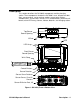
4. Put the GX-2009 in the charging base. Tabs at the top and bottom of the charging base retain the instrument. Retaining Tabs RKI GX-2009 POWER MODE AIR H2S CO %LEL O2 Figure 17: Putting the GX-2009 in the Charging Base 5. While the unit is being charged, the red charging LED on the top face of the charger is on. 6. When the charging LED turns off, the GX-2009’s batteries are fully charged. It takes approximately 3 hours to recharge a fully discharged battery set. 7.
“memory effect” and the run time of the instrument may be decreased. If you notice this effect with your instrument, use the REFRESH function described in “Discharging the Batteries with the REFRESH Function” on page 45 to discharge your batteries before recharging them. Replacing the GX-2009’s NiMH Batteries WARNING: Replace the batteries in a non-hazardous environment. Replace the battery set when it no longer holds a charge. 1. Verify that the GX-2009 is off. 2.
5. As you pull the top of the rear case away from the front case, you will feel a slight click as the bottom of the rear case separates from the bottom of the front case. Pull the rear case away from the front case. Keep the instrument flat and steady so that the batteries do not drop out of the case. Figure 20: Removing the Rear Case 6. The batteries will be visible in the front case on the main circuit board. Once the front case is removed, they are no longer held in place and can be easily removed.
Holes match up with tabs on bottom of battery. Holes match up with tabs on bottom of battery. Figure 22: Front Case With Batteries Removed 8. Replace each battery with a new one. Note the polarity markings on the circuit board and batteries when installing each battery. Tabs on the bottom of each battery match up with holes in the circuit board. 9. Reinstall the rear case to the front case with the four case screws.
Replacing the Scrubber Filters WARNING: Replace the scrubber filters in a non-hazardous environment. Sensor Cover Retainer Sensor Cover Sensor Retainer Gasket RKI GX-2009 POWER MODE AIR H2 S CO %LEL H2S Removal Filter Disk O2 Charcoal Filter Disk Figure 23: Removing the Sensor Retainer and Replacing the Scrubber Filters 1. Verify that the GX-2009 is off. 2. Unscrew the two screws that secure the sensor retainer and sensor cover retainer to the GX-2009 and remove them. 3.
7. Reattach the sensor cover retainer in its original position. It should snap into place onto the sensor retainer. 8. Replace the two screws that you removed in Step 2 above to secure the sensor retainer and sensor cover retainer to the GX-2009. Replacing the Sensor Cover WARNING: Replace the sensor cover in a non-hazardous environment. 1. Verify that the GX-2009 is off. 2. Unscrew the two screws that secure the sensor retainer and sensor cover retainer to the GX-2009 and remove them. 3.
02 %LEL O2 H2S H2S CO CO %LEL POWER MODE AIR GX-2009 RKI Figure 24: Removing the Sensor Retainer to Replace a Sensor 4. Remove the sensor from its socket. 5. Carefully insert the replacement sensor in the socket. CO H2S HC O2 Line up slots in H2S and CO sensors with tabs in case.
CAUTION: When replacing a sensor, verify that the sensor is properly aligned with its socket before inserting it into the socket. The CO and H2S sensors have alignment slots which match up with alignment tabs in the sockets. The combustible gas sensor has two non-polarized contacts which must line up with the contacts in the socket. Forcing a sensor into its socket may damage the sensor or the socket. 6. Snap the sensor retainer back onto the case, then secure it to the GX2009 with the two screws.
Parts List Table 7 lists replacement parts and accessories for the GX-2009.
Table 7: Parts List Part Number Description 49-2170RK-04 Charging station with AC adapter for four instruments, 115 VAC 49-2170RK-05 Charging station with AC adapter for five instruments, 115 VAC 49-2171RK Charging station with 12 VDC vehicle plug adapter 71-0158RK GX-2009 Portable Gas Monitor Operator’s Manual 71-0162RK GX-2009 User Setup Program Operator’s Manual 71-8002RK GX-2009 Product CD, includes Data Management Program, User Setup Program, and all operator’s manuals 81-GX01HSCO One 58
Table 7: Parts List Part Number Description 81-1004RK Regulator, fixed flow, 0.