Model GX-2001 Operator’s Manual Part Number: 71-0053RK Revision: J Released: 10/21/10 www.rkiinstruments.
WARNING Read and understand this instruction manual before operating instrument. Improper use of the gas monitor could result in bodily harm or death. Periodic calibration and maintenance of the gas monitor is essential for proper operation and correct readings. Please calibrate and maintain this instrument regularly! Frequency of calibration depends upon the type of use you have and the sensor types.
Warranty RKI Instruments, Inc., warrants the Model GX-2001 sold by us to be free from defects in materials, workmanship, and performance for a period of two years from the date of shipment from RKI Instruments, Inc. This includes the instrument and the original sensors. Replacement parts are warranted for 1 year from the date of their shipment from RKI Instruments, Inc. Any parts found defective within their warranty period will be repaired or replaced, at our option, free of charge.
Table of Contents Introduction . . . . . . . . . . . . . . . . . . . . . . . . . . . . . . . . . . . . . . . . . . . . . . . . . . . . . . . . . . 1 Specifications. . . . . . . . . . . . . . . . . . . . . . . . . . . . . . . . . . . . . . . . . . . . . . . . . . . . . . . . . 2 Description . . . . . . . . . . . . . . . . . . . . . . . . . . . . . . . . . . . . . . . . . . . . . . . . . . . . . . . . . . . 4 Case . . . . . . . . . . . . . . . . . . . . . . . . . . . . . . . . . . . . . . . . . . . . . . . .
Calibration . . . . . . . . . . . . . . . . . . . . . . . . . . . . . . . . . . . . . . . . . . . . . . . . . . . . . . . . . . 24 Setting the Zero Readings for All Target Gasses . . . . . . . . . . . . . . . . . . . . . . . . 24 Single Calibration . . . . . . . . . . . . . . . . . . . . . . . . . . . . . . . . . . . . . . . . . . . . . . . . 25 Auto Calibration. . . . . . . . . . . . . . . . . . . . . . . . . . . . . . . . . . . . . . . . . . . . . . . . . . 28 Maintenance . . . . . . . . . . . . . . . . .
Introduction Using an advanced detection system consisting of four gas sensors, the Model GX-2001 Personal Four-Gas Monitor detects the presence of combustible gas, oxygen (O2), carbon monoxide (CO), and hydrogen sulfide (H2S) simultaneously.
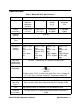
Specifications Table 1: Model GX-2001 Specifications Model Name Model GX-2001 Target Gas Combustibles (Methane calibration standard) Oxygen (O2) Hydrogen Sulfide (H2S) Carbon Monoxide (CO) Range (Increment) 0-100% LEL (1% LEL) 0-40.0 vol% (0.1 vol%) 0-100 ppm (0.
Table 1: Model GX-2001 Specifications Model Name Other Accessories Model GX-2001 • Charging Station with PC Communication Function for Datalog Downloading • Communication Computer Cable • • • • • Dimensions and Weight 3 • Specifications Communication Software (Windows® 95, 98, NT) Automatic Calibration Station Hand Aspirated Sample Draw with Hose and Probe Wrist Strap (included with every unit) Neck Strap Dimensions: 2.8 (H), 2.2 (W), 1.1 (D) inches Weight: Approximately 6 oz.
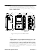
Description This section describes the components of the Model GX-2001. These components include the Model GX-2001’s case, sensors, LCD, control buttons, printed circuit boards, alarm lights, buzzer/vibrator, battery pack, belt clip, and battery charger.
Beneath the control buttons is the buzzer/vibrator, which is located inside the unit. On the right side of the Model GX-2001 are the diffusion ports for the gas sensors located inside the case. These sensors are, from top to bottom (and are marked on the case), O2, HC (combustible gases), CO, and H2S. On the left side of the case are two brass recharging contacts, which are used when the unit is placed in the battery charger, and on top of the case are two alarm lights.
Oxygen Sensor The O2 sensor is a galvanic type of sensor. A membrane covers the cell and allows gas to diffuse into the cell at a rate proportional to the partial pressure of oxygen. The oxygen reacts in the cell and produces a voltage proportional to the concentration of oxygen. The voltage is measured by the Model GX-2001’s circuitry, converted to a measurement of gas concentration, and displayed on the LCD.
Sensor Cover The sensor cover is white and protects the scrubber filters and sensors from dust and water. It fits over all the sensor diffusion ports and is secured in place by the sensor cover retainer. If the sensor cover becomes dirty, the accuracy of the GX-2001 will be affected. Replace the sensor cover if it appears dirty. LCD The LCD is visible through the GX-2001’s front panel. Target gas concentrations, the time, battery condition, and alarm indications are displayed on the LCD.
Table 2: The Control Buttons of the Model GX-2001 Button DISP AIR Function • Turns the LCD back light on. • Displays the next target gas when the unit is in Measuring Mode. • Enters Time Adjustment Mode with the MODE/ POWER button. • Decreases settings when the unit is in Alarm Adjustment Mode or Time Adjustment Mode. • Toggles between field calibration and auto calibration when the unit is in Calibration Mode. • Turns the LCD back light on. • Adjusts LCD readings when the a Demand Zero is performed.
Buzzer/Vibrator A solid-state electronic buzzer/vibrator is mounted inside the front case of the Model GX-2001. The buzzer/vibrator sounds and vibrates for gas alarms, and it sounds for unit malfunctions, low battery voltage, and as an indicator during normal use of the many display options of the Model GX2001. Battery Pack Inside the Model GX-2001 is either a Ni-cad or Ni-MH battery pack that supplies 2.4 V to the unit.
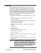
Start Up This section explains how to start up the Model GX-2001 and to get it ready for operation. Start-up Procedure 1. Press and hold the MODE/POWER button for one second to turn on the Model GX-2001 and to activate its LCD. The alarm lights flash, the buzzer sounds, and the vibrator vibrates. 2. The Model GX-2001 tests all elements of the LCD, then displays the year, month, day, and time before displaying the battery voltage. The buzzer sounds again after the battery voltage is displayed.
Performing a Demand Zero Before using the Model GX-2001, it is a recommended to set the zero reading (demand zero) for the target gasses to ensure accurate gas readings in the monitoring environment. 1. Find a fresh-air environment. This is an environment free of toxic or combustible gasses and of normal oxygen content (20.9%). 2.
Operation This section describes the normal operation of the Model GX-2001. It explains how the unit can be used to display peak gas readings of the four target gasses and to display STEL and TWA readings for H2S and CO. It covers important issues regarding combustible gas detection. It also covers alarm indications and use of the aspirator adapter accessory.
4. To return to Measuring Mode, normal operation, press and release the MODE/POWER button until the normal screen is displayed. NOTE: While in Peak Reading Mode, if no control button has been pushed for about 15 seconds, the Model GX-2001 returns to Measuring Mode automatically. Displaying STEL and TWA Readings With the Model GX-2001, you can display STEL and TWA readings for H2S and CO.
Combustible Gas Detection There are two issues that must be considered when checking for combustible gas. • The combustible sensor will respond to any combustible gas. The standard calibration for the GX-2001 combustible channel is to methane (CH4). If the instrument is to be used to monitor for a different combustible gas, such as hexane or propane, it should be calibrated to that gas. The table below lists the conversion factors for several hydrocarbon gasses if the GX-2001 is calibrated to methane.
• The GX-2001 provides the combustible sensor with some protection against exposure to high levels of combustible gas. It does this by turning off the combustible sensor power temporarily when it determines that an over scale (more than 100% LEL) concentration of combustible gas is present that may damage the sensor. Nevertheless, concentrations of combustible gas of more than 100% LEL can still affect the zero level or calibration of the combustible sensor if the concentration is high enough.
The table below summarizes the types of alarms produced by the Model GX-2001. Table 4: Alarm Types and Indications Alarm Type Alarm 1 Concentration of gas rises above the first alarm point, or for O2, falls below the low point setting. Alarm 2 Concentration of gas rises above second alarm point, or for O2, rises above the high point setting. TWA or STEL Concentration of CO or H2S rises above the TWA or STEL alarm point setting. Over Range LCD Indications Other Indications • Name of gas displayed.
Table 4: Alarm Types and Indications Alarm Type Sensor Failure LCD Indications • Name of gas sensor displayed. • Gas reading replaced by FAIL. Other Indications Double Pulsing Tone (two pulses in quick succession) Multiple Alarms If more than one gas alarm is activated, the LCD shows the concentration of the gas that triggered the last alarm. To see the concentration of the other gasses, press the DISP button until the gas of interest is displayed.
Responding to Alarms This section describes response to gas, over range, battery, and sensor failure alarms. Responding to Gas Alarms 1. Determine which gas alarm has been activated. 2. Follow your established procedure for an increasing gas condition or a decreasing oxygen condition. 3. Reset the alarm using the MODE/POWER button once the alarm condition has been cleared.
NOTE: Alarms and the back light feature consume battery power and reduce the amount of operating time remaining. Responding to Sensor Failure Alarms 1. Determine which sensor has triggered the sensor failure alarm. 2. Try calibrating the sensor first, as described in “Calibration,” before replacing it. 3. If the sensor failure continues, replace the sensor as described in “Replacing a Sensor.” 4. If the sensor failure condition continues after you have replaced the sensor, contact RKI Instruments, Inc.
1. Turn on the GX-2001 as directed in the Startup section. 2. Attach the adapter plate of the aspirator adapter to the sensor side of the instrument. 3. Screw the probe onto the threaded end of the 10 ft. hose. 4. Attached the 10 ft. hose and probe to the aspirator bulb. 5. Insert the end of he probe into the area to be sampled. 6. Squeeze and release the aspirator bulb 15 times. Monitor the readings and note if any alarms occur.
Displaying and Setting the Alarm Points The Model GX-2001 allows you to display and set the alarm points of the four target gasses. Each of the target gasses has both a low (Alarm 1) and high (Alarm 2) alarm setting. Two gasses, CO and H2S, have STEL and TWA alarm points. The alarm point for oxygen is measured as a percentage of oxygen in the atmosphere.
Display and Adjust the Alarm Points 1. Make sure the Model GX-2001 is turned off. The LCD should be blank. 2. Press and hold the AIR button, then press and hold the MODE/POWER button. 3. As soon as segments appear on the display (approximately one second), release the AIR button. When the unit “beeps,” release the MODE/POWER button to put the Model GX-2001 into Alarm Point Adjustment Mode. The LCD should show the Alarm 1 setting for O2 and the battery level. Target gas O2 Battery charge 19.
Setting the Time and Date The Model GX-2001 allows you to set the time and date. 1. Make sure the Model GX-2001 is turned off. The LCD should be blank. 2. Press and hold the DISP button, then press and hold the MODE/ POWER button to put the Model GX-2001 into Time Adjustment Mode. Release the buttons when the unit beeps. The LCD shows the year, month, day, and time. The year is flashing at the top of the LCD. 2000 Year 11.13 Month Hour Day 2 1 : 06 Minute Figure 5: LCD in Time Adjustment Mode 3.
Calibration This section covers the calibration of the Model GX-2001. Setting the zero reading is described first followed by single calibration and auto calibration. For single calibration, you are told what is needed to complete the task, how to assemble the calibration kit, and how to set the span readings of the four target gasses. The same topics are covered for auto calibration. WARNING: Use a 0.5 LPM (liters per minute) fixed flow regulator when calibrating.
4. While you are pressing the AIR button, the LCD displays “Hold,” a prompt for you to keep pressing the AIR button. 5. When the zero readings have been set, the LCD displays “Adj,” which prompts you to release the AIR button. Single Calibration This section tells you how to calibrate the Model GX-2001 using the single calibration (CAL) menu. Preparation Before you calibrate the Model GX-2001, you must set the zero readings as described in “Setting the Zero Readings for All Target Gasses.
Assembling the Calibration Kit WARNING: Calibrate the Model GX-2001 in a non-hazardous environment. To Fixed Flow Regulator Calibration Tubing RKI 02 O2 Flow HC GX-2001 MO D E D ISP Adapter Plate HC AI R PO W ER CO CO H2S H2S Figure 6: Assembling the Calibration Kit and Attaching It to the Model GX-2001 1. Attach the adapter plate to the unit. It snaps onto the sensor area. 2. Attach the calibration tubing to the adapter plate, then attach the opposite end of the tubing to the regulator.
Setting the Span Readings for All Target Gasses When setting the span readings manually for one gas sensor at time, you will calibrate each gas sensor individually. 1. Make sure you have set the zero readings for all the target gasses and have set up the calibration kit as described in the procedure above. If you are going to calibrate all the target gasses, start with O2 followed by H2S, CO, and HC. 2. Make sure the Model GX-2001 is off. 3.
Auto Calibration This section tells you how to calibrate the Model GX-2001 using the auto calibration (AUTO CAL) menu. Preparation Before you calibrate the Model GX-2001, you must set the zero readings as described in “Setting the Zero Readings for All Target Gasses.” You will also need the supplies listed below. Calibration kits from RKI Instruments, Inc. are available for this purpose (see “Parts List”).
5. Press the MODE/POWER button again. You may now check the current auto calibration settings of the unit’s gas sensors, beginning with oxygen. In the upper left corner of the LCD, the word, “CAL,” and the name of the gas sensor being checked will flash alternately. The LCD will also show the current auto calibration setting (e.g., 12.0% for O2). To skip checking the autocalibration settings, go to step 6.
Maintenance This section describes troubleshooting procedures for the Model GX-2001. It also describes how to recharge the Model GX-2001’s battery pack as well as how to replace the unit’s battery, sensor cover, and gas sensors. WARNING: RKI Instruments, Inc. recommends that service, calibration, and repair of RKI instruments be performed by personnel properly trained for this work. Replacing sensors and other parts with original equipment does not affect the intrinsic safety of the instrument.
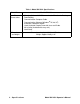
Table 6: Troubleshooting the Model GX-2001 Symptoms Probable Causes Recommended Action • The LCD shows abnormally high or low readings but other gas detection instruments do not. • The Model GX2001 may need to be recalibrated. • The sensor for the affected channel(s) may need replacement. 1. Recalibrate the unit. 2. Replace the sensor for the affected channel(s). 3. If the difficulties continue, contact RKI Instruments for further instruction.
Recharging the GX-2001’s Battery Pack WARNING: To prevent ignition of a hazardous atmosphere, batteries must only be changed or charged in an area known to be nonhazardous. CAUTION: To be used with RKI Ni-cad battery pack p/n 49-1602RK or NiMH battery pack 49-1605RK. Charge only with RKI charger p/ n 49-2155RK, 49-2156RK, or 49-2163RK. 1. Verify that the Model GX-2001 is off. 2. Plug the battery charger’s AC power cord into an electrical outlet.
Replacing the Battery Pack WARNING: Replace the battery pack in a non-hazardous environment. Replace the battery pack when it no longer holds a charge. 1. Verify that the Model GX-2001 is off. 2. On the left or right side of the Model GX-2001, unscrew two of the screws securing the belt clip retaining pins to the unit. 3. Carefully slide out the small pins holding the belt clip to the unit by grasping them with your fingers. 4.
CAUTION: When replacing the battery, be certain to insert the bottom of the battery (the thickest and largest part) first into the housing of the Model GX-2001 before inserting the top. Inserting the top of the battery first before the bottom may damage the circuit board underneath. 2nd: Push in Plac e G ently Re move Pack F rom T his End 1st: Put in Place Shown Without Clip & Rear Cover Plate Figure 8: Inserting a New Battery into the Model GX-2001 7.
Replacing the Scrubber Filters Sensor Cover Retainer Sensor Cover H2S Removal Filter Disk RKI 02 HC GX-2001 MODE DISP AIR POWER CO H2S Charcoal Filter Disk H2S Removal Filter Disk Figure 9: Removing the Sensor Retainer and Replacing the Scrubber Filters 1. Verify that the Model GX-2001 is off. 2. Unscrew the two screws that secure the sensor retainer and sensor cover retainer to the Model GX-2001 and remove them. 3.
Replacing the Sensor Cover WARNING: Replace the sensor cover in a non-hazardous environment. 1. Verify that the Model GX-2001 is off. 2. Unscrew the two screws that secure the sensor retainer and sensor cover retainer to the Model GX-2001 and remove them. 3. Using a small flat blade screwdriver, gently pry each side of the sensor cover retainer away from the sensor retainer. 4. Remove the sensor cover, then insert the replacement cover. 5. Reattach the sensor cover retainer in its original position.
Replacing a Sensor WARNING: Replace the sensors in a non-hazardous environment. 1. Verify that the Model GX-2001 is off. 2. Unscrew the two screws that secure the sensor retainer (with the sensor cover retainer still attached) to the Model GX-2001 enough to remove the sensor retainer with the screws still in place. RKI 02 02 HC GX-2001 MOD E D ISP AI R PO W ER CO CO H2S H2S Figure 10: Removing the Sensor Retainer to Replace a Sensor 3. Remove the sensor from its socket. 4.
Shown w/out Sensor Retainer 02 HC 02 HC CO CO H 2S H2S Line up slots in H2S and CO sensors with tabs in case. Figure 11: Replacing the Sensors and Their Locations in the Model GX-2001 5. Place the sensor retainer in its original position, then secure it to the Model GX-2001 with the two screws. 6. Start up the Model GX-2001 by pressing and holding the MODE/ POWER button. 7. Calibrate the new sensor as described in the calibration section of this manual. Rotating the Belt Clip 1.
Parts List Table 7 lists replacement parts and accessories for the Model GX-2001.
Table 7: Parts List Part Number Description 81-GX01CO-LV One 34 ltr.