Model GX-2001 Data Logging Software With Calibration Station User’s Guide Part Number: 71-0064RK Revision: E Released: December 11, 2002 RKI Instruments, Inc. • 33248 Central Ave.
Warranty RKI Instruments, Inc., warrants gas alarm equipment sold by us to be free from defects in materials and workmanship, and performance for a period of one year from date of shipment from RKI Instruments, Inc. Any parts found defective within that period will be repaired or replaced, at our option, free of charge.
Table of Contents Technical Notice on Updating Software . . . . . . . . . . . . . . . . . . . . . . . . . 5 Introduction . . . . . . . . . . . . . . . . . . . . . . . . . . . . . . . . . . . . . . . . . . . . . . . . 6 System Requirements . . . . . . . . . . . . . . . . . . . . . . . . . . . . . . . . . . . . . . . 8 Specifications . . . . . . . . . . . . . . . . . . . . . . . . . . . . . . . . . . . . . . . . . . . . . . 8 Overview of the GX-2001 Data Logging Software . . . . . . . . . . . . . . . . .
Precautions . . . . . . . . . . . . . . . . . . . . . . . . . . . . . . . . . . . . . . . . . . . 43 Required Items for Calibration . . . . . . . . . . . . . . . . . . . . . . . . . . . . . 43 Calibrating a Three-Gas Model GX-2001 . . . . . . . . . . . . . . . . . . . . 44 Preparing for Calibration . . . . . . . . . . . . . . . . . . . . . . . . . . . . . . . . . 45 Auto-Calibrating the Model GX-2001. . . . . . . . . . . . . . . . . . . . . . . . 46 Manual Calibration. . . . . . . . . . . . . . . . . . . .
Technical Notice on Updating Software If you are updating your GX-2001 Downloading Software and your existing software is version 01523 or earlier, DO NOT DELETE YOUR OLD GX-2001 SOFTWARE OR THE OLD SOFTWARE FOLDER. DATA SAVED USING VERSION 01523 OR EARLIER IS NOT READABLE USING VERSION 01610 OR LATER. BEFORE INSTALLING THE NEW SOFTWARE, CHANGE THE NAME OF THE OLD SOFTWARE FOLDER SO IT IS DIFFERENT THAN THE NAME OF THE NEW SOFTWARE FOLDER TO BE INSTALLED.
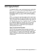
Introduction Using an advanced detection system consisting of four gas sensors, the Model GX-2001 Personal Four-Gas Monitor detects the presence of combustible gases, oxygen (O2), carbon monoxide (CO), and hydrogen sulfide (H2S) simultaneously.
Before you get started, be sure to review system requirements in the next section. Next read the overview about the GX-2001 Data Logging Software and Calibration Station. CAUTION: The Model GX-2001 detects oxygen deficiency and elevated levels of oxygen, combustible gases, carbon monoxide, and hydrogen sulfide, all of which can be dangerous or life threatening.
System Requirements To use the GX-2001 Data Logging Software and Calibration Station, your personal computer must meet the following requirements: • Operating Systems: Windows® 95, Windows® 98 SE, Windows® ME, Windows® 2000, or Windows NT® 4.0 • Processor: IBM® compatible PC running Pentium® 2, Pentium® 3, or Pentium® 4 processor, or equivalent processor.
Overview of the GX-2001 Data Logging Software The Model GX-2001 is a gas monitoring device for combustible gases, O2, CO, and H2S. It measures combustible gases as a percentage of the lower explosive limit (% LEL), O2 as a straight percentage (%), and H2S and CO as parts per million (ppm). The Model GX-2001 also records STEL and TWA readings for H2S and CO. STEL is an acronym for short-term exposure limit, and it shows the average reading for H2S and CO during the last 15 minutes.
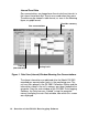
Interval Trend Data Gas concentrations are logged over five minute time intervals in the interval trend data files. Events are saved when they occur. The data may be viewed in table format, as seen in the following figure, or graph format. Gas concentrations Time log (date and time) Provides summary data Warning levels Figure 1. Data View (Interval) Window Showing Gas Concentrations The above information was obtained after the Model GX-2001 recorded gas concentration levels in the monitoring area.
For a given data session (interval data), there must be at least five scheduled logs (every five minutes) for the data to be seen in graph form. If an interval data session has fewer than five scheduled logs, as in Figure 1 above, the graph button is not available for selection.
minutes before and 15 minutes after the event, with the log time every five seconds. When an event occurs and an alarm trend data file is saved in the Model GX-2001, this file remains in the unit’s memory until another event occurs. When another event takes place, the alarm trend data file is overwritten with the information of the new event. Alarm trend data can always be displayed in either table or graph format. The following figure shows a sample alarm trend graph of the four target gases.
Instrument Information and Calibration History Calibration History on the most recent successful calibration for the Model GX-2001 is available on two screens: the Calibration History and the Instrument Information windows. The Instrument Information window also shows warning levels and alarm levels along with STEL and TWA readings. Both windows, with sample data, are shown below. Calibration history data Before and after calibration settings Warning, alarm, STEL, and TWA settings Figure 4.
Before and after calibration settings Figure 5.
A Road Map of the Software The windows on the previous pages are accessed through the Download window of the GX-2001 Data Logging Software. The Download window is the starting point for all GX-2001 Data Logging Software functions, and it is the first screen displayed when you launch the software. The figure below shows the various screens that you can access when you click the icon buttons on the right of the Download window. Figure 6.
Overview of the GX-2001 Calibration Station This section describes the components of the GX-2001 Calibration Station, which is used for down loading information in the Model GX-2001 and for the calibration of that unit. Front Panel Pilot On Off Low Flow Fresh Air Span Gas GX-2001 Calibration Station Flow Figure 7. GX-2001 Calibration Station: Front View The front panel of the GX-2001 Calibration Station has an on/off switch, four indicator lights, a flow meter, and handles.
On/Off Switch. Use this switch to turn on or to turn off the GX2001 Calibration Station. When downloading information only, you do not have to turn on the GX-2001 Calibration Station. Just plug in the Downloading/Charger Station to a 115 VAC wall outlet. Indictor Lights. The Pilot light indicates that power has been turned on (or off) to the GX-2001 Calibration Station. The Low Flow light turns on if the flow to the Calibration Adapter is too low.
Back Panel Particle Filter Charcoal Filter Fuse Holder Fresh Air FlowAdjust Low Flow Alarm Adjustment Screw Span Gas Flow Adjust Fuse 1A, 250V Charger Fresh Air In 115 VAC IN Span Gas In Computer Figure 8. GX-2001 Calibration Station: Back View The back panel is where you make a number of connections and adjust the flow rate of the span gas and fresh air. Fresh Air In Fitting.
Computer Connector. The computer receives its information from the GX-2001 Calibration Station when a DB-9 female/ female extension cable is plugged into this connector and the other end of the cable is plugged into a serial port on the computer. A six foot cable is supplied with the Calibration Station. 115 VAC IN Connector. This connector is for the power cord that is provided with the Calibration Station. Fresh Air Flow Adjustment Valve.
Charger/Downloading Station with Calibration Adapter LED Release Lever Calibration Adapter Locking Button Charger/Downloading Station Pilot On Off Low Flow Fresh Air Span Gas GX-2001 Calibration Station Flow Figure 9. Charger/Downloading Station with Calibration Adapter These units come pre-assembled from the factory and sit on top of the GX-2001 Calibration Station.
There is an LED on the top left of the Charger/Downloading Station, which turns on after the Model GX-2001 has been placed in the Data Logging/Charger Station and the power cord for the Data Logging/Charger Station has been plugged into an electrical outlet. When the Model GX-2001 has been fully charged, this light goes off. The Calibration Adapter is attached to the right side of the Charger/Downloading Station. It routes sample gas over the sensors of the Model GX-2001.
Installing the GX-2001 Data Logging Software 1. Launch Windows®. 2. Exit from all applications and open windows. 3. Insert the GX-2001 Data Logging Software CD into your computer’s CD-ROM drive. A dialog box displays confirming that you have quit all running applications. Click “OK” to continue. 4. Read and accept the software license agreement, then Click “Next.” 5. To install the GX-2001 Data Logging Software in the default directory (C:/Programs/GX-2001), click the Computer Icon.
Launching the Software 1. Click Start on the Windows Icon Tray, then select “Programs/ GX-2001.” 2. Click “GX-2001.” The Download window displays. Figure 10. The Download Window 3. For convenience, make a shortcut of the GX-2001 Data Logging Software program and place it on the Windows desktop. See your Windows documentation for information about making shortcuts.
Setting Up the GX-2001 Calibration Station for Down Loading Data 1. Plug the power cable of the Charger/Downloading Station, which sits on top of the GX-2001 Calibration Station, into a 115 VAC electrical outlet. 2. Connect the data cable to the computer connector on the back of the GX-2001 Calibration Station and connect the other end of this cable to the computer’s serial port. Refer to your computer’s documentation for the location of the serial port. 3.
Down Loading Data from the Model GX-2001 You have the option of down loading data manually or automatically. If you want to download information using the automatic download feature, click the “Automatic Download” checkbox in the Download window before placing the Model GX2001 in the Charger/Downloading Station that sits on top of the GX-2001 Calibration Station.
3. Choose the COM port on the computer to which you have connected the Data Logging/Charger Station. 4. Press the Mode/Power button on the Model GX2001. “Conn” displays on the Model GX-2001 LCD and “GX-2001...Connected Successful.” displays in the Download area of the Download window. 5.
7. After the data has been down loaded successfully, messages are displayed in the Download area of the Download window. (See the figure on the following page.) These messages tell you what type of information has been down loaded. Download messages Use to down load all data Instrument data Use to down load subsets of the data Clear data button Figure 14. Download Messages in the Download Window 8. You can view, print, or save the downloaded information.
Viewing, Printing, Exporting, and Deleting Data You can view instrument information, interval data, alarm data, and calibration history. Interval and alarm data can be printed and saved to a file. Calibration history can be printed. Viewing Instrument Information To view instrument information for the last unit downloaded during a session, click the Instrument Information button on the Download window. The Instrument Information window displays. This screen cannot be printed from the downloading software.
Viewing Interval and Alarm Data To view interval and alarm data, click the Data button on the Download window. The Data window displays. Double-click to see the data files Check to organize files Figure 16. Data Window To see the data, do the following: 1. Double-click the GX-2001 icon in the Data area of the Data window to see the files holding the interval and alarm data. 2. To view interval or alarm data files (not the actual data), click the interval folder or the alarm folder, respectively.
3. Next double-click a file to view its contents, or click the View Data button. 4. When viewing interval data, you can see the information in a table format, graph the data if there are more than five scheduled data points, view the data in summary form, or view the events only. Data that has been graphed shows log time, gas concentration levels, and alarm events. Interval Data Interval Data with Summary Figure 18.
5. When viewing alarm data, you can see it either in table or graph form. Click to print data Click to transfer data to a file Click for a summary of the data Zoom level Cursor feature Figure 19. Alarm Data in Graph Form 6. In graph form, five or more events are required for interval trend data. When viewing interval trend or alarm trend information in graph form, you have several options: • You can choose which gas you want to graph • You can choose the zoom level, or time interval, on the graph.
• Note that the Cursor feature (applies to both interval and alarm data files) allows you to display the log time. As you use the scroll arrow to move across the graph from left to right, readings at specific log times are displayed. 7. To go back and view other data, click the Data button on the Download window. Viewing and Printing Calibration History To view calibration data, click the Calibration History Button on the Download window. The Calibration History window displays. Figure 20.
NOTE: The Model GX-2001 units that are now due for calibration will have calibration dates highlighted in red for the channels that are now due. For the Model GX2001 units that are due for calibration in less than one day the calibration dates are highlighted in orange for the channels that will be due. If the calibration interval is “0,” then all units are always due for calibration and the calibration dates are highlighted in red. • No.
The fields also include the following: Figure 21. Calibration History Information: Calibration Record Option • Gas — Lists the target gas for which the Before, After, and A.Cal readings are displayed. • Before — shows the settings prior to calibration. • After — shows the settings after calibration. • A. Cal. — lists the auto-calibration setting for each channel of a Model GX-2001 unit. If a unit passes its calibration, the “After” column should match the “A. Cal.” column.
• Cal. Due (Days) — shows when calibration is due in days (e.g., “Remaining 25 days” means that calibration is due in 25 days, and “Now” means that calibration is due immediately). To print calibration data for any instrument, select the Need Calibration or Calibration Date option when in the Calibration History Window and then right click on the calibration record you want to print. Select the Print option, then select the printer and click OK to print the calibration record.
To export interval and alarm data, do the following: 1. From the Display window, double-click the data file you want to export. (You can also click (select) the file you want to export, then click the View Data button.) You can only export one file at a time. The Data View window displays. 2. There are two ways to export. If you click the To Clipboard button, the table or graph displayed is copied to the clipboard. The clipboard file can then be pasted into a word processing or spreadsheet program.
Deleting Data and Changing the Password To delete data files, place the cursor on the file and click with the right mouse button. When the Delete box appears, right click it and click the yes button when the Delete Sample window appears. To delete data files, select the Need Calibration or Calibration Date option, place the cursor on the file and click with the right mouse button. When the Print/Delete box appears, right click on Delete.
Changing Data Logging Parameters To make changes to settings stored in the Model GX-2001, use the Set window of the GX-2001 Data Logging Software. Follow the steps below to make these changes. 1. Launch the GX-2001 Data Logging Software. 2. Insert the Model GX-2001 into the GX-2001 Calibration Station. 3. Turn on the Model GX-2001 to make a connection between the Model GX-2001 and the computer. 4.
5. Click the Set button in the Download window to display the Set window. Use the Set window to change the instrument information stored in the Model GX-2001. Click to upload changes to the Model GX-2001 Figure 24. Set Window 6. To change the serial number, station ID, or user ID stored in the Model GX-2001, click the field you wish to change (e.g., user ID), use the backspace key to remove the current entry, then type the new information. 7.
9. Exit the Set window by either clicking the Download button, if you have more units to calibrate or to enter instrument information for, or by clicking the Exit button, which will close the GX-2001 Data Logging Software. 10.Next, turn off the Model GX-2001 by pressing and holding the Mode button on the unit. Then remove the unit from the Calibration Station.
Changing the Appearance of Data Logging Reports To change how data is displayed in reports (e.g., text fonts and graph colors), use the Set window of the GX-2001 Data Logging Software. Follow the steps below to make these changes. 1. Launch the GX-2001 Data Logging Software. 2. Click the Set button in the Download window to display the Set window. Click to change font type Choose these options to change the graph colors for the target gases Figure 25.
3. Specify new fonts for data reports by clicking the button with the name of a font inscribed upon it. This action will display the Font window. Choose the font type, style, and size for your data reports. Figure 26. Font Window 4. Select the colors used to graph the various target gases in the alarm data report. To do this, click the buttons on the left side of the Set window in the “Font and Color” area of the screen. Figure 27. Color and Custom Color Windows 5.
Calibrating the Model GX-2001 with the Calibration Station The GX-2001 Data Logging Software allows you to calibrate the Model GX-2001 using the GX-2001 Calibration Station. During the calibration process, you set the zero and span readings for the Model GX-2001. You can accomplish this task by using the Automatic Calibration feature in the Download window. Precautions During the calibration process, you may be using low levels of both toxic and combustible gases.
Demand Flow Regulator. This item comes with the GX-2001 Calibration Station. It screws into the top of the calibration gas cylinder and controls the flow of gas from the cylinder to the GX2001 Calibration Station. Gas Cylinder. A four-gas, 58 liter cylinder comes as standard equipment with the GX-2001 Calibration Station. It contains 50% LEL methane (CH4), 12% oxygen (O2), 50 ppm carbon monoxide (CO), and 25 ppm hydrogen sulfide (H2S). The balance gas is nitrogen (N2). Polyurethane Tubing.
Preparing for Calibration 1. Plug the power cable of the GX-2001 Calibration Station into a 115 VAC electrical outlet. 2. Plug the power cable of the Data Logging/Charger Station into a 115 VAC electrical outlet. 3. Connect one end of the data cable to the computer connector on the back of the GX-2001 Calibration Station. Connect the other end of this cable to the computer’s serial port. Refer to your computer’s documentation for the location of the serial port. 4.
8. Connect the polyurethane tubing from the regulator to the Span Gas In fitting on the back of the GX-2001 Calibration Station. 9. Make sure the Calibration In and Calibration Out tubing is properly attached to the Calibration Adapter. This tubing was connected at the factory. Auto-Calibrating the Model GX-2001 1. Make sure you have properly setup the GX-2001 Calibration Station following the instructions under “Preparing for Calibration.” 2.
6. Lock the Calibration Adapter onto the Model GX-2001 by pressing the black button on the right side of the Calibration Adapter. CAUTION: Make sure to lock the calibration adapter onto the GX-2001 before continuing or an inaccurate calibration will result. Release Lever, Push Down To Release GX-2001 Locking Button Push To Lock Pilot On Off Low Flow Fresh Air GX-2001 Calibration Station Span Gas Flow Figure 29.
7. Turn on the Model GX-2001 by pressing and holding the Mode button on the Model GX-2001 for about one second. The Downloading Software will retrieve instrument information. If the Model GX-2001 is due for calibration, it will be calibrated. If the Model GX-2001 is not due for calibration, the unit will not be calibrated. If you still want to calibrate the unit, see the next section, “Manual Calibration.” NOTE: If the Cal.
Manual Calibration If the Model GX-2001 is not due for calibration, you can still calibrate the unit with the Calibration Station using the Cal. Unit Calibration button on the Download window. NOTE: If manually calibrating a unit more than once in an hour, see the Calibration Interval section below for precautions. 1. Make sure you have properly setup the GX-2001 Calibration Station following the instructions under “Preparing for Calibration.” 2.
9. To begin calibration, click the “Cal. Unit Calibration” button on the Download window. Figure 30. Choosing the Cal. Unit Calibration Option 10.After the Model GX-2001 has been calibrated, remove it from the Charger/Downloading Station by pressing down on the metal release lever located on the right side of the Calibration Adapter. 11.Place another Model GX-2001 in the Data Logging/Charger Station if you have other unit(s) to calibrate. Repeat steps 5 – 10 above. 12.
Flow Rate The recommend flow rate for fresh air flow is 1.0 SCFH. and 0.8 SCFH for span gas flow. The low flow alarm is set at 0.4 ± 0.1 SCFH, and will sound if the flow rate reaches this level. If the flow rate drops below the recommended flow rate during calibration, you can adjust the flow rate by making adjustments using a flat head screw driver to either the Fresh Air Flow Adjust Valve or the Span Gas Flow Adjust Valves on the back of the GX-2001 Calibration Station.
Calibration Interval In the Set Menu of the GX-2001 Data Logging Software, there is a data field called Cal. Interval. The value entered into this data field is stored in the computer, not the GX-2001. It indicates the calibration interval, in days, for the Model GX-2001. If you set the Cal. Interval to 0, for example, the calibration will always be due whenever you place the Model GX-2001 in the GX-2001 Calibration Station.
2. Place the GX-2001 into the Charger/Downloading Station. 3. While the unit is being charged, the red LED on the top face of the Charger/Downloading Station is on. 4. When the red LED turns off, the GX-2001’s battery pack is fully charged. It takes approximately 90 minutes to recharge a fully discharged battery pack. 5. To verify whether the battery pack is fully recharged, remove the unit from the battery charger, then press the MODE/POWER button to start up the unit.
should consider replacing the charcoal filter once a year, and in the case of H2S or hydrocarbon contamination, more frequently, like every three-to-six months, depending on the level of the contamination. To change one of the filters, remove the rubber fittings on both ends of the filter, then carefully remove the filter from the metal brackets that hold it to the back of the GX-2001 Calibration Station.
Adjusting the Low Flow Alarm The factory set low flow alarm setting is 0.4 SCFH (±0.1). The low flow alarm can be adjusted using the low flow adjustment screw, which is located in the upper left corner of the back panel. It is accessible through a hole in the panel. Use a small flathead screwdriver to make the adjustment. To adjust the low flow setting, do the following: 1.
8. Use the fresh air adjustment valve to set the flow to 1.0 SCFH. NOTE: If the calibration station switches over to drawing span gas before you are able to complete the adjustment, use the span gas adjustment valve to make flow adjustments. 9. Click the Cancel button on the screen to abort the calibration sequence. 10.Turn off the calibration station and exit the downloading software.
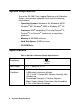
Spare Parts List Table 2: Spare Parts List Part Number Description 06-1252RK Polyurethane tubing, 1/4-inch OD x 1/8-inch ID 06-1248RK Polyurethane tubing, 5/16-inch OD x 3/16-inch ID 17-0601RK Rubber elbow (used on filters and calibration adapter) 33-0163RK Particle filter 33-6095RK Charcoal filter 43-4140RK Fuse, 1/4-inch x 1 1/4-inch, 1A, 250V 47-1013RK Power cord 47-5006RK Downloading cable, DB-9 female to DB-9 female, straight through, 6 foot 49-2156RK Downloading charger w/ cable an