Model GP-01 Combustible Gas Monitor With Self-Resetting Alarms Operator’s Manual Part Number: 71-0105RK Revision: 0 Released: 1/17/05 RKI Instruments, Inc. 33248 Central Ave.
Warranty RKI Instruments, Inc., warrants the Model GP-01 Single LEL Gas Monitor sold by us to be free from defects in materials, workmanship, and performance for a period of two (2) years from the date of shipment from RKI Instruments, Inc. This includes the instrument and the original sensor. Replacement parts are warranted for one (1) year from the date of their shipment from RKI Instruments, Inc.
Table of Contents Introduction . . . . . . . . . . . . . . . . . . . . . . . . . . . . . . . . . . . . . . . . . . . . . . . . . . . . . . . . . . 5 Specifications. . . . . . . . . . . . . . . . . . . . . . . . . . . . . . . . . . . . . . . . . . . . . . . . . . . . . . . . . 6 Description . . . . . . . . . . . . . . . . . . . . . . . . . . . . . . . . . . . . . . . . . . . . . . . . . . . . . . . . . . . 7 Protective Rubber Boots . . . . . . . . . . . . . . . . . . . . . . . . . . . . . . . . . . . . . . .
Maintenance . . . . . . . . . . . . . . . . . . . . . . . . . . . . . . . . . . . . . . . . . . . . . . . . . . . . . . . . . 25 Troubleshooting. . . . . . . . . . . . . . . . . . . . . . . . . . . . . . . . . . . . . . . . . . . . . . . . . . 25 Replacing or Charging the Batteries . . . . . . . . . . . . . . . . . . . . . . . . . . . . . . . . . . 26 Replacing the Combustible Sensor. . . . . . . . . . . . . . . . . . . . . . . . . . . . . . . . . . . 29 Replacing the Sensor Filters . . . . . . . . . . . .
Introduction Using an advanced microprocessor controlled detection system, the Model GP-01 Single LEL Gas Monitor detects the presence of combustible gas (e.g., methane, CH4) as a percentage of LEL (lower explosive limit). The Model GP-01’s compact size and easy-to-use design makes it ideally suited for a wide range of applications, including sewage treatment plants, tunnels, hazardous waste sites, petrochemical facilities, oil fields, mines, and chemical plants.
Specifications Table 1: Model GP-01 Specifications Target Gas Combustible Gas, Methane (CH4) Calibration Standard Detection Range 0-100% LEL (1% LEL Increments) Detection Principle Catalytic Combustion Method Sampling Type Diffusion Response Time T90 in 30 seconds Indication 7-Segment Digital LCD Gas Alarms (Factory Settings) • • • Other Alarms Sensor Failure, Low Battery, Dead Battery, System Failure, and Calibration Failure Operating Temperature & Humidity - 20°C — 50°C, Below 90% RH (Non
Description This section describes the components of the Model GP-01. These components include the GP-01’s protective rubber boots, case, membrane retainer and filter disks, sensor retainer, sensor, LCD, control buttons, printed circuit boards, alarm lights, buzzer, vibrator, and batteries.
Protective Rubber Boots A protective rubber boot is installed over each end of the GP-01. The sensor end boot fits over the sensor cover end of the GP-01 and the battery end boot fits over the battery cover end of the GP-01. If you have a Ni-cad battery pack in your GP-01, you must remove the battery end boot to insert the GP-01 in the charger. Case The Model GP-01’s sturdy, high-impact plastic case is blue in color. The case is suitable for use in many environmental conditions, indoors and out.
Alligator and Belt Clips The GP-01 is available with two types of clips, the alligator clip and the belt clip. Both are illustrated in Figure 2 below. Belt Clip Alligator Clip Figure 2: Alligator & Belt Clips The alligator clip can be used to attach the GP-01 to clothing or a belt. Teeth in the clip’s jaws prevent the unit from slipping off. The belt clip is used to easily clip the GP-01 on a belt. Membrane Retainer and Filter Disks The membrane retainer is held in place by a single Phillips screw.
they turn dark brown. Frequency of replacement depends on how often the Model GP-01 is exposed to H2S and on the concentration of H2S in the environment. If installed, check the condition of the H2S scrubber filter disks every three months. NOTE: See “Combustible Gas Detection” on page 15 for a discussion of when the H2S scrubber disks should be used and how they affect detection of certain gasses. The sensor cover fits into a larger recessed area and covers the two H2S scrubber filter disks (if installed).
LCD The LCD is visible through the front of the case. When the GP-01 is in Measuring Mode, the target gas concentration, battery condition, and alarm indications are displayed on the LCD. Various other items are displayed when the LCD is in other modes, such as Calibration Mode. When either of the two control buttons are pressed, the LCD backlight comes on for 20 seconds. Control Buttons Below the LCD are two control buttons: POWER/MODE and AIR. The POWER/MODE button turns the Model GP-01 on and off.
NOTE: The printed circuit boards contain no user serviceable parts. Alarm Lights The Model GP-01 has two red LED alarm lights. They alert you to combustible gas, low battery, and sensor failure alarms. The smaller of the two lights is square, has a frosted plastic cover, and is located at the top of the unit to the left of the membrane retainer.
Start Up This section explains how to start up the Model GP-01 and to get it ready for operation. CAUTION: Before each day’s usage sensitivity must be tested on a known concentration of the combustible target gas, typically methane, equivalent to 25 - 50% of full scale. Accuracy must be within -0 - + 20% of concentration. Accuracy may be corrected by following the calibration instructions in the calibration section on p. 22. Start-up Procedure 1.
Turning Off the Model GP-01 1. Press and hold the POWER/MODE button for about five seconds to turn off the unit. The buzzer will sound while the POWER/MODE button is being pressed before the unit turns off. 2. Release the button when the LCD is blank. The unit is off. Operation This section describes the normal operation of the GP-01 in Measuring Mode and how to display the peak reading. It also covers alarm indications.
NOTE: The peak gas reading is cleared automatically when the Model GP-01 is turned off. 1. The unit must be in Measuring Mode. The current gas concentration should be displayed on the LCD. 2. Press and release the POWER/MODE button to enter Peak Gas Display Mode. The LCD backlight will activate and the LCD will display the peak gas reading. A small peak symbol is displayed in the upper left corner of the LCD. .
Table 3: LEL Hydrocarbon Conversions LEL Conversion Factor (Methane Calibration) Gas Gas LEL Conversion Factor (Methane Calibration) Acetone 1.92 Iso Butane 1.56 Acetylene 2.00 MEK 1.92 Benzene 2.00 Methane 1.00 Ethane 1.25 Methanol 1.65 Ethanol 1.75 Pentane 1.35 Ethylene 1.20 Propane 1.52 Heptane 1.92 Propylene 1.33 Hexane 1.65 Toluene 2.00 Hydrogen 1.00 Xylene 2.00 IPA 2.
Alarms This section covers alarm indications and how to respond to an alarm condition. Alarm Indications The Model GP-01 will sound an alarm, flash its alarm lights, and vibrate when the target gas concentration rises above the low alarm point. The Model GP-01 also sounds an alarm, flashes its alarm lights, and vibrates when the high alarm point is reached. In addition, the Model GP-01 has a low battery warning, a dead battery alarm, an over range alarm, a sensor failure alarm, and a system failure alarm.
Table 4: Alarm Types and Indications Alarm Type LCD Indications Other Indications Dead Battery Alarm • Gas reading replaced by FAIL. • Battery icon flashes. • Double pulsing tone (two pulses in quick succession) occurs once a second. Sensor Failure • Gas reading replaced by FAIL. • Double pulsing tone (two pulses in quick succession) once a second System Failure • Gas reading replaced by FAIL. • SYS displays below FAIL.
3. Calibrate the Model GP-01 as described in the calibration section of this manual. 4. If the over range condition continues, you may need to replace the sensor. 5. If the over range condition continues after you have replaced the sensor, contact RKI Instruments, Inc. for further instructions. Responding to Battery Alarms WARNING: The Model GP-01 is not operational as a gas monitoring device during a dead battery alarm.
Alarm Points The Model GP-01 allows you to display and set the alarm points. There is a low alarm point and a high alarm point. Both are rising alarms, meaning that the alarm condition is triggered when the gas concentration rises to the alarm point. The alarm point factory settings are summarized below: Table 5: Alarm Points of the Model GP-01 Low Alarm High Alarm 10% LEL Increasing 50% LEL Increasing The low alarm point can be adjusted between a range of 0% LEL and 50% LEL.
quick succession increases the low alarm point one number at a time. Pressing and holding the AIR button increases the low alarm point by ten percentage points at a time. NOTE: If you pass the desired alarm point setting, continue increasing the alarm point until it reaches the maximum setting, at which point the alarm point number will “wrap around” to its minimum setting. 5. Press and release the POWER/MODE button to display the high alarm point in the LCD.
Calibration This section covers the calibration of the Model GP-01. Setting the fresh air reading is described first followed by setting the span reading. You are also told what is needed to complete the task and how to assemble the calibration kit. WARNING: Use a 0.5 LPM (liters per minute) fixed flow regulator when calibrating. Using a different flow rate may adversely affect the accuracy of the calibration. Calibration Frequency If the GP-01 passes the response test described in Startup on p.
• You will need a gas cylinder with an appropriate concentration of the target gas. The Model GP-01’s calibration value must match the gas concentration in the calibration cylinder, otherwise the calibration will not be accurate. CAUTION: Do not use a gas mix that includes H2S to calibrate the GP-01. • To carry out the calibration, you will need a fixed-flow regulator with a flow rate of 0.
If you want to cancel the calibration while in Span Adjustment Mode, press and hold the AIR key for 3 seconds and the unit will not make any span adjustments and begin its startup sequence. NOTE: If one of the control buttons is not pressed within 10 minutes, the unit will return to Measuring Mode automatically. 6. Attach the regulator to the gas cylinder. The fixed-flow regulator automatically begins introducing the calibration sample to the sensor. 7. Let the gas flow for two minutes.
Maintenance This section describes troubleshooting procedures for the Model GP-01. It also describes how to change or charge the Model GP-01’s batteries as well as how to replace the unit’s gas sensor and filter disks. WARNING: RKI Instruments, Inc. recommends that service, calibration, and repair of RKI instruments be performed by personnel properly trained for this work. Replacing sensors and other parts with original equipment does not affect the intrinsic safety of the instrument.
Table 6: Troubleshooting the Model GP-01 Symptoms Probable Causes Recommended Action • “FAIL” displays during span adjustment. • The calibration value may not match the cylinder gas concentration. • The sample gas is not reaching the sensor because of a bad connection. • The calibration cylinder may be out of gas or is outdated. • The sensor may need replacement. 1. Check all calibration tubing for leaks or for any bad connections. 2. Make sure the Model GP01 has been properly set up for calibration.
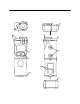
To Replace the Alkaline Batteries or Ni-Cad Battery Pack NOTE: The Ni-Cad battery pack will have a typical service life of 500 charging cycles minimum before it needs replacement. 1. Verify that the Model GP-01 is off. 2. Remove the battery end protective rubber boot. %LEL GP-01 POWER MODE AIR 3. Rotate the captive battery cover screw counterclockwise to remove battery compartment door. Figure 7: Removing the Battery Compartment Door 4.
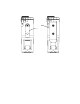
POWER MODE AIR GP-01 %LEL Red Charging LED Figure 8: Putting GP-01 Into Charging Station 5. When a full charge has been reached, approximately 40 minutes, the red LED on the charging station will turn off. Remove the Model GP-01 from the charging station and unplug the charging station’s power cord from the AC outlet. To Recharge the Ni-cad Battery Pack Out of the GP-01 The GP-01 battery pack may be recharged directly in the charger without being in a GP-01.
Battery Pack Red Charging LED Figure 9: Putting Battery Pack Into Charging Station 3. When a full charge has been reached, approximately 40 minutes, the red LED on the charging station will turn off. Remove the battery pack from the charging station and unplug the charging station’s power cord from the AC outlet. Replacing the Combustible Sensor WARNING: Replace the sensor in a non-hazardous environment. 1. Verify that the Model GP-01 is off. 2. Remove the sensor end protective rubber boot. 3.
4. Carefully remove the old sensor from the sensor socket. NOTE: Note the orientation of the old sensor before you remove it. 5. Carefully insert the replacement sensor in the socket. Make sure the sensor face with the yellow colored ring is facing up and that the sensor contacts line up with the contacts in the sensor socket.
POWER MODE AIR GP-01 %LEL H2S Scrubber Disks Sensor Cover Figure 12: Replacing the Sensor Filters 3. Rotate the membrane retainer about one-quarter turn counterclockwise to remove it from the sensor retainer (the top of the unit). 4. Carefully remove the old filter or filters from the recess in the senor retainer. NOTE: Install the new sensor filter or filters into the recess. If H2S scrubber filters are used, put them in first. Make sure they are properly seated in the recess.
Parts List Table 7 lists replacement parts and accessories for the Model GP-01. Table 7: Parts List Part Number Description 06-1248RK Calibration kit tubing (specify length in feet) 07-6009RK Gasket for battery cover 10-1099RK Screw, M2X 4mm pan head Phillips, stainless steel, for membrane retainer 10-1105RK Screw, M2X 8mm pan head Phillips, stainless steel, for sensor retainer 10-1141RK Screw,M2.5 x 3mm pan head Phillips, stainless steel, for alligator and belt clip installation.
Table 7: Parts List Part Number Description 81-1003RK Regulator, fixed flow, 0.5 LPM, for 17/34 liter steel cylinder 81-1004RK Regulator, fixed flow, 0.