Model GD-K8A Diffusion Detector Head Operator’s Manual Part Number: 71-0081RK Revision: A Released: 3/1/11 www.rkiinstruments.
WARNING Read and understand this instruction manual before operating detector. Improper use of the detector could result in bodily harm or death. Periodic calibration and maintenance of the detector is essential for proper operation and correct readings. Please calibrate and maintain this detector regularly! Frequency of calibration depends upon the type of use you have and the sensor types.
Product Warranty RKI Instruments, Inc. warrants gas alarm equipment sold by us to be free from defects in materials, workmanship, and performance for a period of one year* from the date of shipment from RKI Instruments, Inc. Any parts found defective within that period will be repaired or replaced, at our option, free of charge. Parts must be returned to RKI Instruments, Inc. for repair or replacement.
Table of Contents Overview . . . . . . . . . . . . . . . . . . . . . . . . . . . . . . . . . . . . . . . . . . . . . . . . . . . . . . . . . . . . . . . . . . . 1 Specifications. . . . . . . . . . . . . . . . . . . . . . . . . . . . . . . . . . . . . . . . . . . . . . . . . . . . . . . . . . . . . . . . 1 Description . . . . . . . . . . . . . . . . . . . . . . . . . . . . . . . . . . . . . . . . . . . . . . . . . . . . . . . . . . . . . . . . . . 2 Housing Assembly . . . . . . . . . . . . . . . . . . . . .
Overview This manual describes the Model GD-K8A diffusion 4 - 20 mA transmitter detector head. This manual also describes how to install, start up, maintain, and calibrate the GD-K8A when it is used with a gas monitoring controller. A parts list at the end of this manual lists replacement parts and accessories for the GD-K8A. Specifications Table 1 lists specifications for the GD-K8A. Table 1: Specifications Target Gas & Detector Range Refer to the RKI Instruments Inc.
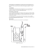
Description This section describes the components of the GD-K8A. The GD-K8A consists of three major components: the housing assembly, the sensor unit and the auto sensor keeper (ASK). The sensor unit is secured in the housing by two screws. It can be removed by loosening these two screws for sensor or amplifier replacement. The ASK is also secured in the housing by two screws.
The housing has two mounting flanges, one at the top and one at the bottom. The top mounting flange has a slotted hole in the middle and the bottom mounting flange has two holes, one in each corner. These holes are used for mounting the GD-K8A to a vertical surface. Cable Bushing A cable bushing on the bottom left of the housing allows you to route wiring from a controller to the two point external wiring terminal strip in the housing. The cable bushing accommodates a .35 inch to .43 inch diameter cable.
Sensor Bracket The painted steel sensor bracket is used to install the sensor and amplifier into the GDK8A housing. It is secured to the housing with two screws. The mounting holes in the bracket are slotted allowing removal of the bracket for sensor or amplifier replacement without removing the two mounting screws. Sensor The sensor is mounted in the sensor bracket with two screws through the back of the sensor bracket.
Installation This section describes how to install the GD-K8A at the monitoring site. This section includes procedures to mount the GD-K8A in the monitoring environment and wire the GD-K8A to a controller. Mounting the GD-K8A CAUTION: The GD-K8A is suitable for installation in indoor areas where general purpose equipment is in use. 1. Select a mounting site that is representative of the monitoring environment. Consider the following when you select the mounting site.
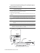
2. Use three #10 screws through the mounting holes in the mounting flanges at the top and bottom of the housing to mount the GD-K8A to a vertical surface (see Figure 3). Wiring the GD-K8A to a Controller WARNING: Always verify that the power source is off before making wiring connections or adjustments. 1. Place the controllers power switch in the off position. 2. Turn off power to the controller. 3. Guide a two conductor shielded cable through the cable bushing at the bottom of the GD-K8A.
5. Connect the ground bolt to a locally available earth ground. 6. Connect the cable shield’s drain wire to an available earth (chassis) ground at the controller. The grounding screw on each controller conduit hub is an example of an earth (chassis) ground. Start Up This section describes procedures to start up the GD-K8A and place it into normal operation. Introducing Incoming Power 1. Complete the installation procedures described earlier in this manual. 2.
Maintenance This section describes maintenance procedures for the GD-K8A. It includes preventive maintenance and troubleshooting procedures. Preventive Maintenance This section describes a preventive maintenance schedule to ensure the optimum performance of the GD-K8A. It includes daily, monthly, and quarterly procedures. Daily Verify a display reading of 0 at the controller. Investigate significant changes in the display reading. Monthly NOTE: Verifying the response of the GD-K8A may cause alarms.
Performing the response test 1. Screw the calibration cylinder onto the fixed flow regulator. 2. Turn the regulator’s on/off knob counterclockwise to open it. Gas will begin to flow. 3. Allow gas to flow for two minutes and verify the reading is within ± 20% of the response reading you determined earlier. NOTE: If the reading is not within ± 20% of the correct response reading, calibrate the GD-K8A as described in the Calibration section of this manual. 4.
Slow or No Response/Difficult or Unable to Calibrate Symptoms • The GD-K8A responds slowly or does not respond during the monthly response test. • Unable to accurately set the zero or response reading during the calibration procedure. • The GD-K8A requires frequent calibration. NOTE: Under “normal” circumstances, the GD-K8A requires calibration every 3 - 6 months. Some applications may require a more frequent calibration schedule.
4. Loosen the two screws that secure the sensor bracket to the housing, then remove the sensor unit from the housing. 5. Remove the two screws on the back of the sensor bracket that secure the sensor to the bracket and remove the sensor with amplifier from the bracket. 6. Disconnect the ASK from the amplifier. A cable leading from the ASK plugs into a connector near the top of the amplifier. 7.
Calibration This section describes how to calibrate the GD-K8A. It includes procedures to prepare for calibration, set the zero reading, set the response reading, and return to normal operation. Preparing for Calibration NOTE: This procedure describes calibration using a fixed flow regulator with an on/off knob. 1. Put the controller into its calibration program or disable external alarms to avoid unwanted alarms during calibration.
7. Remove the milliampmeter test clips from the output check pins. 8. Close the housing door. 9. Allow time for the gas reading to return to normal, then return the controller to normal operation. NOTE: If the gas reading does not return to normal before returning the controller to normal operation, unwanted alarms may occur. 10. Store the components of the calibration kit in a safe and convenient place. 11. Verify that the controller display reading decreases and stabilizes at 0.
Parts List Table 4 lists replacement parts and accessories for the GD-K8A. Table 2: Parts List Part Number Description GD-K8A-XXX GD-K8A transmitter (specify target gas when ordering) 49-1120RK AA size alkaline batter, 1.
Table 2: Parts List Part Number Description ES-K233-HF Sensor, hydrogen fluoride ES-K239C-O3 Sensor, ozone Model GD-K8A Diffusion Detector Head • 15