
User Manual


Model GD-K7D24X Sampl e Draw Transmitter • 4
2. Place the controller’s and GD-K7D24X’s power switches in the OFF position.
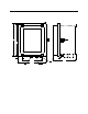
3. Use the conduit hubs at the bottom of the GD-K7D24X for routing shielded cable into
the enclosure and then route the cable through the cable bushing on the GD-K7D2.
See the Installation sections of the GD-K7D2 Operator’s Manual for wiring
connections between the GD-K7D2 and the controller.
Two conduit hubs are provided on the enclosure. One of them may be used for AC
power if a 115 VAC GD-K7D2 is installed. Plug any unused conduit hub with a 3/4”
conduit plug.
4. Connect the cable shield’s drain wire to a chassis ground at the controller, but do not
connected it at the GD-K7D24X.
CAUTION: Leave the cable shield’s drain wire insulated and disconnected at the GD-K7D24X.
You will connect the opp osite end o f the cable shield’s drain wire at the co ntroller.
CAUTION: At the controller, do not route power and GD-K7D24X wiring through the same
conduit hub. T he power cable may disrupt th e transmission o f the GD-K7D2’s
signal to the controller.
Start Up
See the GD-K7D2 Operator’s Manual for GD-K7D2 startup instructions.
Operation
See the GD-K7D2 Operator’s Manual for an operational description of the GD-K7D2 that
is mounted inside the enclosure.
Maintenance/Calibration
See the GD-K7D2 Operator’s Manual for maintenance and calibration instructions. Use
the inlet fitting on the NEMA 4X enclosure to apply gas instead of the fittings inside the
enclosure on the GD-K7D2.
Parts List
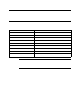
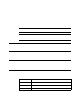
Table 4 lists replacement parts and accessories for the GD-K7D2.
Table 2: Parts List
Part Number Description
06-1273RK 1/4” O.D. x 1/8” I.D. Teflon PTFE tubing
17-4820RK Sample fitting, 1/4” tube bulkhead union
18-0107RK 3/4” conduit hu b