
User Manual


Model GD-K7D24X Sampl e Draw Transmitter • 2
Description
This section describes the components of the GD-K7D24X . It cons ists of the enclos ur e an d
a GD-K 7D2 mounted insi de.
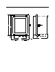
Figure 1: Outline & Mounting Dimensions/Component Location
A hydrophobic sample filter is also provided with the GD-K 7D24X for installation near
the inlet fitting. The filter scrubs particulates out of the sample stream and keeps water
and ma ny other liquids from entering the GD-K7D24X f low system.
Enclosure
The enclosure is a type NEMA 4X plastic enclosure designed for use in areas that are
subject to rain or hos ing down. A mounting f oot is installed in each corner. Two sample
fittings are mounted on the bottom right of the enclosure and two 3/4” conduit hubs are
mounted to the left of the sample fittings.
Sample Fittings
The inlet fitting is on the bottom right of the enclosure and the exhaust fitting is to the left
of the inlet fitting. The fittings accept 1/4”O.D. x 1/8” I.D. Teflon tubing.
Conduit Hubs
Two 3 /4” conduit hubs are located to the left of the sample fittings. They are used for
routing wiring into the enclosure by using conduit or an appropriate cable bushing.
2.51
8.227.01
1.43
Inle t Fittin g
Exhaust Fitting
9.88
Ø .34, 4X
11.23
1
1.75
3/4" Conduit
Hub, 2X