Model GD-K7D24X Supplement to the GD-K7D2 Operator’s Manual Part Number: 71-0086RK Revision: A Released: 3/1/11 www.rkiinstruments.
WARNING Read and understand this instruction manual before operating detector. Improper use of the detector could result in bodily harm or death. Periodic calibration and maintenance of the detector is essential for proper operation and correct readings. Please calibrate and maintain this detector regularly! Frequency of calibration depends upon the type of use you have and the sensor types.
Product Warranty RKI Instruments, Inc. warrants gas alarm equipment sold by us to be free from defects in materials, workmanship, and performance for a period of one year* from the date of shipment from RKI Instruments, Inc. Any parts found defective within that period will be repaired or replaced, at our option, free of charge. Parts must be returned to RKI Instruments, Inc. for repair or replacement.
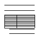
Overview This supplement describes the differences and additional features of the Model GDK7D24X compared to the GD-K7D2. It also describes how to install, startup, maintain, and calibrate the GD-K7D24X. Specifications Table 1 lists specifications for the GD-K7D24X. Table 1: Specifications Target Gas & Detector Range Refer to the RKI Instruments Inc.
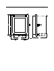
Description This section describes the components of the GD-K7D24X. It consists of the enclosure and a GD-K7D2 mounted inside. Ø .34, 4X 11.75 11.23 1.43 2.51 7.01 8.22 Inlet Fitting 9.88 3/4" Conduit Hub, 2X Exhaust Fitting Figure 1: Outline & Mounting Dimensions/Component Location A hydrophobic sample filter is also provided with the GD-K7D24X for installation near the inlet fitting.
GD-K7D2 The GD-K7D2 sample draw detector head is mounted to a plate inside the enclosure. The GD-K7D2 sample fittings are factory connected to the sample fittings on the NEMA 4X enclosure. There are two types of GD-K7D2’s that can be mounted in the enclosure: a 24VDC version and a 115 VAC version. See the GD-K7D2 Operator’s Manual for a complete description of the GD-K7D2. Installation This section describes how to install the GD-K7D24X at the monitoring site. Mounting the GD-K7D24X 1.
2. Place the controller’s and GD-K7D24X’s power switches in the OFF position. 3. Use the conduit hubs at the bottom of the GD-K7D24X for routing shielded cable into the enclosure and then route the cable through the cable bushing on the GD-K7D2. See the Installation sections of the GD-K7D2 Operator’s Manual for wiring connections between the GD-K7D2 and the controller. Two conduit hubs are provided on the enclosure. One of them may be used for AC power if a 115 VAC GD-K7D2 is installed.