Model GD-K7D2 (24 VDC) Sample Draw Detector Operator’s Manual Part Number: 71-0078RK Revision: A Released: 3/1/11 www.rkiinstruments.
WARNING Read and understand this instruction manual before operating detector. Improper use of the detector could result in bodily harm or death. Periodic calibration and maintenance of the detector is essential for proper operation and correct readings. Please calibrate and maintain this detector regularly! Frequency of calibration depends upon the type of use you have and the sensor types.
Product Warranty RKI Instruments, Inc. warrants gas alarm equipment sold by us to be free from defects in materials, workmanship, and performance for a period of one year* from the date of shipment from RKI Instruments, Inc. Any parts found defective within that period will be repaired or replaced, at our option, free of charge. Parts must be returned to RKI Instruments, Inc. for repair or replacement.
Table of Contents Overview . . . . . . . . . . . . . . . . . . . . . . . . . . . . . . . . . . . . . . . . . . . . . . . . . . . . . . . . . . . . . . . . . . . 1 Specifications. . . . . . . . . . . . . . . . . . . . . . . . . . . . . . . . . . . . . . . . . . . . . . . . . . . . . . . . . . . . . . . . 1 Description . . . . . . . . . . . . . . . . . . . . . . . . . . . . . . . . . . . . . . . . . . . . . . . . . . . . . . . . . . . . . . . . . . 2 Cover. . . . . . . . . . . . . . . . . . . . . . . . . . .
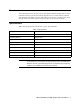
Overview This manual describes the 24 VDC version of the Model GD-K7D2 sample draw 4 - 20 mA transmitter detector head. This manual also describes how to install, start up, maintain, and calibrate the GD-K7D2 when it is used with a gas monitoring controller. A parts list at the end of this manual lists replacement parts and accessories for the GD-K7D2. Specifications Table 1 lists specifications for the 24 VDC version of the GD-K7D2.
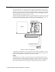
Description This section describes the components of the GD-K7D2. The GD-K7D2 consists of three separate sections: the cover, the detection unit, and the installation bracket. The detection unit (front section) includes the flow system and gas detection components. The L-shaped installation bracket (rear section) includes installation components including a terminal strip, tube fittings and a card edge connector socket.
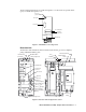
The flow light and flowmeter are visible through the cover. The flow rate potentiometer (pot) is accessible through the cover. Flow rate potentiometer Flow light ADJ. FLOW Flowmeter ID card holder Gas name card holder GAS DETECTOR MODEL GD-K7D Thumbscrew Figure 2: GD-K7D2 Cover Components Detection Unit The detection unit includes the main circuit board, flowmeter, gas sensor, amplifier, pump, and lithium battery pack.
Main Circuit Board The main circuit board includes the flow light, flow rate pot, ON/OFF switch and fuse. The end of the board at the rear of the detection unit plugs into a socket on the installation bracket. Flow light The flow light is at the top left corner of the detection unit (see Figure 2 and 3). The green flow light is on when the GD-K7D2’s flow rate is at an acceptable flow rate. If the flow rate drops below or rises above the acceptable flow rate, the flow light turns off.
output during start-up and calibration procedures. Gain pot The gain pot is below the zero pot. It is used to make coarse span adjustments. The gain pot is factory set and for adjustment by a field service technician only. Another factory adjust pot is located below the gain pot. Do not adjust this pot. Output check pins Two output check pins [marked 1 (+) and 2 (-)] are below the pots.
Socket A card edge connector socket on the back of the bracket mates with the main circuit board on the detection unit. External Wiring Terminal Strip A seven point terminal strip is located below the socket and used for wiring the GD-K7D2 to a controller. A jumper is normally factory installed between the second and third terminals from the right. This jumper is installed when the GD-K7D2 is used with a controller that does not have a flow alarm circuit and flow alarm terminals for wiring to the GD-K7D2.
Installation This section describes how to install the GD-K7D2 at the monitoring site. This section includes procedures to disassemble the GD-K7D2, mount the GD-K7D2, connect sample lines to the GD-K7D2, and wire the GD-K7D2 to a controller. Disassembling the GD-K7D2 1. Loosen the thumbscrew on the front of the housing cover, then remove the cover from the detection unit and installation bracket. 2.
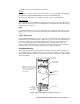
NOTE: All measurements in inches 2.76 ADJ. FLOW 6.46 .59 1.57 7.5 1.97 1.38 GAS DETECTOR MODEL GD-K7D 1.54 FRONT VIEW REAR VIEW 6.02 0.36 SIDE VIEW Figure 5: Mounting the GD-K7D2 Connecting Sample Lines to the GD-K7D2 1. When shipped from the factory, the tube nut, ferrule, and tube insert are shipped uninstalled and the open fittings are plugged with protective rubber plugs. Remove the protective plugs from the gas in and gas out fittings. 2.
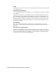
Tubing Insert Ferrule Tube Nut 4 mm x 6 mm PTFE Teflon Tubing Figure 6: Installing Tubing in the Sample Fittings 3. Connect the sample filter to the tube. The sample filter has flexible tube stubs on each end. Push one end onto the sample tube. 4. Connect another length of sample tubing to the other side of the sample filter and route it to the sampling area. Be sure not to exceed the maximum sample tubing length listed in Table 2.
CAUTION: Avoid loops or slumps in the incoming sample line. To reduce response time, keep the incoming sample line as short as possible. See the Table 2 above for maximum sample tubing lengths. 5. Attach 4 mm I.D. x 6 mm O.D. Teflon PTFE sample tubing to the gas out fitting. Route the opposite end of the tubing to an open area where the sample can safely disperse or to an exhaust duct.
5. If using a controller with flow alarm terminals, connect the remaining two wires to an appropriate 24 VDC power source as shown in Figure 9.
7. Connect the cable shield’s drain wire to an available earth (chassis) ground at the controller. The grounding screw on each controller conduit hub is an example of an earth (chassis) ground. Assembling the GD-K7D2 1. Position the detection unit so the unit’s main circuit board is aligned with the socket near the top of the installation unit and the internal plumbing is aligned near the bottom of each unit. 2.
3. Use small test clips to connect a milliampmeter to the output check pins. 4. Verify a reading of 4.0 mA on the milliampmeter. If necessary, use the zero pot to adjust the milliampmeter reading to 4.0 mA. CAUTION: Do not adjust the span pot at this time unless a full calibration is performed. The GD-K7D2 is factory calibrated before shipment. 5. Remove the milliampmeter test clips. 6.
Maintenance This section describes maintenance procedures for the GD-K7D2. It includes preventive maintenance and troubleshooting procedures. Preventive Maintenance This section describes a preventive maintenance schedule to ensure the optimum performance of the GD-K7D2. It includes daily, monthly, and quarterly procedures. Daily 1. Verify that the flow light on the front of the GD-K7D2 is on. If it is off, see the Troubleshooting section below. 2.
Performing the response test NOTE: This procedure describes a response test using the RKI calibration kit that incudes a “demand flow” regulator. A calibration kit that uses a gas collection bag is also available. Contact RKI Instruments, Inc., for more information concerning the gas collection bag accessory. 1. Disconnect the incoming Teflon sample tubing from the sample filter. 2. Connect the calibration kit sample tubing from the regulator to the sample filter.
• The GD-K7D2’s ON/OFF switch is in the OFF position. • The GD-K7D2 is malfunctioning. Recommended action 1. At the GD-K7D2, set the correct flow rate with flow rate potentiometer. 2. If you cannot set the correct flow rate, check the sample lines for obstructions or kinks. 3. Verify that the GD-K7D2 wiring is correct and secure. The Installation section of this manual describes GD-K7D2 wiring connections. 4. Verify that the ON/OFF switch is in the ON position. 5.
Storing the GD-K7D2 The GD-K7D2 has a circuit on the main board that keeps a bias voltage on the gas sensor whenever there is no incoming power, such as during shipment, storage, or power outages. This circuit is powered by the lithium battery pack. If the lithium battery pack is dead when power to the GD-K7D2 is turned off or is lost, then the bias voltage normally on the sensor during operation will not be applied to the sensor.
3. If providing 24 VDC to the GD-K7D2 from a source other than the controller, turn off the power source. 4. Place the GD-K7D2’s ON/OFF switch in the OFF position. 5. Loosen the thumbscrew on the front of the housing cover, then remove the cover from the detection unit and installation bracket. 6. Rotate the clear plastic cover on the right side of the detection unit towards you to allow access to the amplifier and sensor. 7. A metal snap-in bracket holds the sensor in place.
8. A metal snap-on bracket holds the pump in place. A tab on the bracket is accessible on the right side of the detector unit. Push the bracket tab back and away from the pump until the bracket snaps back and releases the pump. 9. Gently pull the pump towards the back of the detector unit until it disengages from the detector unit. 10. Disconnect the pump cable from the pump connector on the main board in the top of the detector unit and remove the cable from cable retainer near the connector.
calibration frequency of every 6 months is adequate. If an application is very demanding, for example if the environment is not well controlled, then more frequent calibration than every 3 months may be necessary. Calibration This section describes how to calibrate the GD-K7D2. It includes procedures to prepare for calibration, set the zero reading, set the response reading, and return to normal operation.
Setting the Zero Reading 1. Connect the calibration kit sample tubing from the sample filter to the regulator. NOTE: The GD-K7D2 pump automatically begins pulling the calibrating sample from the calibration cylinder when the calibration kit is completely assembled and connected to the GD-K7D2’s sample filter. 2. Allow the GD-K7D2 to draw gas for two minutes and verify a reading of 4.0 mA. If necessary, use the zero pot to adjust the reading to 4.0 mA. 3.
Parts List Table 4 lists replacement parts and accessories for the GD-K7D2. Table 3: Parts List Part Number Description GD-K7D2-XXXX-24V GD-K7D2 transmitter (specify target gas when ordering), 24 VDC version 30-1016RK Replacement pump, w/cable & connector, for 24 VDC GD-K7D2 33-0165RK Replacement filter, without flexible tubing stub on ends 33-0165RK-01 Replacement filter, with flexible tubing stub on ends 43-4155RK Fuse, 5 mm x 20 mm, 2 amp, fast acting 49-1410RK Lithium battery pack, 3.
Table 3: Parts List Part Number Description ES-23R-NH3 Sensor, ammonia ES-K233-CL2 Sensor, chlorine ES-K233-F2 Sensor, fluorine ES-K233-HCL Sensor, hydrogen chloride ES-K233-HF Sensor, hydrogen fluoride ES-K233-O3 Sensor, ozone Model GD-K7D2 (24 VDC) Sample Draw Transmitter • 23