
User guide


Model GD-K7D2 (115 VAC) Sample Draw Transmitter • 11
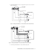
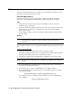
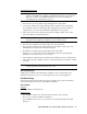
5. Connect the remaining two wires to an appropriate AC power source as shown in
Figure 8 and Figure 9.
Figure 8: Wiring the GD-K7D2 to a Controller Without Flow Alarm Terminals
Figure 9: Wiring the GD-K7D2 to a Controller With Flow Alarm Terminals
6. Connect the ground terminal to a locally available earth ground.
AC In
FLOW
ALARM
+
+
4-20 mA
External Wiring
Terminal Strip
Factory Installed Jumper
Cable Shield
4 - 20 mA In (FB)
+ 24 VDC
115 VAC
Controller, Typical
AC In
FLOW
ALARM
+
4-20 mA
External Wiring
Terminal Strip
Cable Shield
4 - 20 mA In (FB)
+ 24 VDC
115 VAC
Controller, Typical
Flow Alarm