
Instruction Manual


PT2E-1052
10
3−4.
Name of each part & functions
3−4−1.
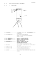
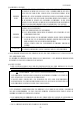
Front view
②
③ ①
④
⑤
⑥
⑦ ⑧ ⑨
① LED indicator…………………… It indicates the gas concentration.(used at
maintenance)
② PW/TR light(Green) ……… For both the power and trouble.
Lighting :The power is on. Normal operation.
Flashing :Trouble
③ ALM1 light(Yellow) ………… It turns ON at (1st) gas alarming.
④ ALM 2 light(Red) …………… It turns ON at (2nd) gas alarming.
(ALARM 1 is also ON).
⑤ SKIP light(Green) …………… It turns ON during the skip mode.
(Detection being suspended).
It turns flashing at the maintenance mode.
⑥ Flowmonitor ………………… For sample flow confirmation. The standard rate is
500mL/min.
⑦ Knurling type screw…………… It is used at opening/ closing the cover.
⑧ Tubing for sampling ………… GAS IN : Tubing for sample gas in.
GAS OUT: Tubing for sample gas out.
⑨ Cable inlet ………………… For the power supply cable, output signal and relay
output.