GD-K71D Sample Draw Detector Head Operator’s Manual Released: 5/19/08 www.rkiinstruments.
PT2E-1052 INDEX 1.PRODUCT OUTLINE 1−1. Preface ……………………………………………………………………… 3 1−2. Application for use ………………………………………………………… 3 1−3. Identification of each signal word ………………………………………… 3 2.IMPORTANT INSTRUCTION FOR THE SAFETY 2−1. Danger items………………………………………………………………… 4 2−2. Warning items………………………………………………………………… 4 2−3. Caution items………………………………………………………………… 5 3.PRODUCT FUNCTION 3−1. External drawing……………………………………………………………… 3−2. Product composition 3−2−1 Major components…………………………………………………… 3−2−2 Unit deta
PT2E-1052 5−5. Maintenance and adjustment 5−5−1. Maintenance mode………………………………………………… 5−5−2. Zero adjustment…………………………………………………… 5−5−3. Confirmation of alarm level ……………………………………… 5−5−4. Alarm test ………………………………………………………… 5−6. How to finish operation……………………………………………………… 26 27 28 29 30 6.KINDS OF ALARM AND ITS FUNCTION 6−1. Kinds of alarms …………………………………………………………… 6−2. Gas alarm 6−2−1. Gas alarm action.
PT2E-1052 1.PRODUCT OUTLINE 1−1.Preface First of all, we wish to express our heartfelt thanks for your purchase of our intelligent gas detector GD-K71D. This manual is just a guide book to operate our gas detector GD-K71D. Your kind reading of this manual is requested not only for first user but for already experienced staff. 1−2.Application for use This is a fixed type toxic gas detector to be used in semiconductor manufacturing factories, etc.
PT2E-1052 2. IMPORTANT INSTRUCTION FOR THE SAFETY 2−1.Danger items DANGER This is not an explosion proof detector. Never to detect high concentration gas beyond their lower explosive limit. 2−2.Warning items WARNING ○ Power source Before turning the power on, check that the supplied voltage is within the specified voltage. Then, turn the power on . ○ Necessity of grounding Do not cut the wire for protective ground both inside and outside of instrument.
PT2E-1052 WARNING ○ Treatment at gas alarming It is very dangerous if the instrument detects the gas exceeded the alarm points. Take any treatment based on your judgment at that time. 2−3.Caution items CAUTION ○ Do not use a walky-talky around the instrument. The indication might be affected by the electromagnetic wave generated by the walky-talky if it is used near the instrument. When the walky-talky is used, be away enough from the instrument not to affect.
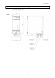
PT2E-1052 3.PRODUCT FUNCTION 3−1.External drawing Display Cable inlet 6 Cable inlet
PT2E-1052 3−2.Product composition 3−2−1.Major components This detector is composed of the following units.
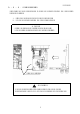
PT2E-1052 3−2−2.Unit detaching After taking the cover out, procedure to detach the detector unit from the wall mounting bracket is as follows. 1. Bring down the lever at the lower part of detector unit. 2. Remove the detector unit from the wall mounting bracket. *NOTE Perform the things above opposite to assemble the unit. When the wiring is arranged, detach the detector unit first. Bring down this lever ! CAUTION When the detector unit is being taking out, take care not to drop it.
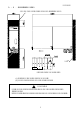
PT2E-1052 3−3.Installation pitch Keep the space of this oblique part as the installation space. Wall Fig. 1: Dimension of mounting pitch (1)Install the wall mounting bracket on the wall. (2)Put the detector unit on the wall mounting bracket. ! CAUTION Confirm that the detector unit is surely fixed to the wall mounting bracket after finishing the job. If it is not surely fixed, the detector unit might drop and cause injury or damage itself.
PT2E-1052 3−4.Name of each part & functions 3−4−1.Front view ② ③ ④ ⑤ ① ⑥ ⑦ ⑧ ⑨ ① LED indicator…………………… It indicates the gas concentration.(used maintenance) ② PW/TR light(Green) ……… For both the power and trouble. Lighting :The power is on. Normal operation. Flashing :Trouble ③ ALM1 light(Yellow) ………… ④ ALM 2 light(Red) …………… ⑤ ⑥ ⑦ ⑧ ⑨ at It turns ON at (1st) gas alarming. It turns ON at (2nd) gas alarming. (ALARM 1 is also ON). SKIP light(Green) …………… It turns ON during the skip mode.
PT2E-1052 3−4−2.Inside view 【Front view of detector unit】 ⑫ ⑭ ⑬ 【Front view of wall mounting unit】 【Side view of detector unit】 ⑩ ⑮ ⑪ ⑯ ⑳ ⑰ ⑲ ⑱ ⑩Power switch (POWER) …… ON/OFF switch for power supply(24VDC). ⑪Fuse ……………………….. Fuse for power ⑫MODE switch (Grey)…………. Switch that changes from detection mode to maintenance mode and changes the mode back to the detection mode.
PT2E-1052 3−5.Block Diagram 3−5−1.Electric diagram Amplifier unit Sensor Display (PW/TR)(ALM1)(ALM2)(SKIP) Power supply part Operation part (MODE)(FLOW ADJ.
PT2E-1052 4.HOW TO USE 4−1.Before operation Be sure to keep caution items of use not only for first user but for already experienced staff. If not keep these caution items, the unit may be defective and correct gas detection may not be performed. 4−2.Installation place CAUTION Detection gas sampling from high dusty places. ・Use the designated dust filter to avoid adsorption of gas or influence caused by ambient dust. ・Stop the suction pump before replacing filter.
PT2E-1052 Do not install it where it is difficult to make maintenance Do not install the detector at places where; * It is required to stop operation of the equipment where gas detector is installed at maintenance work. * It cannot make maintenance without taking off a part of equipment. * Casing cannot be removed by pipings, rack, etc. Do not install it in an equipment that grounding construction is not enough. Be sure to ground when install.
PT2E-1052 (3)Lightning measures There is the problem “Lightning”. When make outdoor wiring of cable at factory or plants etc or when make a parallel wiring in the same duct with the cable in from outdoor even at the indoor wiring. If the Lightning lightning is a huge generation source, the cable is a reception antenna surge and there is the case that cable connecting instrument is broken. It is impossible to prevent the generation of lightning.
PT2E-1052 Reference: By the condition of load, CR circuit may be better to install in the contact side but it is required to put in by checking the action of load. SK:Surge absorption filter SK C O I L SK V L O R D V Alarm contact Power supply GD−K71D Relayed relay Power supply (Low voltage relay) −How to think alarm contacts against inductive load− The spec for alarm contact of GD-K71D is described by the conditions of resistive load.
PT2E-1052 4−4.Grounding Make grounding with inside or outside terminals marked E ! WARNING Be sure to make grounding before putting power ON. Bolt for earth Bolt for earth Be sure to make grounding for safety purpose and to keep stable operation of this unit. Do not connect each wire with gas pipe.
PT2E-1052 4−5.Caution at wiring construction CAUTION ・When make wiring construction, take care not to damage the internal electronics circuit. ・When handle the detector unit, put in at horizontal position. If put it vertically, it tends to fall back and damage the detector. ・For power cable, and signal cable, they should not be laid out with motive power cable such as motor etc. ・When use twisted cable, take care not to contact a part of core cable with other core cable.
PT2E-1052 4−6−4.Terminal plate 1 2 + ― 3 + 4 5 6 7 8 9 10 11 * NOTE Terminals 4 & 5 are not in use. 12 Trouble contact ALM2 contact ALM1 contact ― 4∼20mA DC24V 4−7.Example of cable connection 4−7−1.Connection with indicator/alarm unit (EC-583, EC-573A): (3-wire type) ・ ・ GD-K71D Detector EC-583 EC-573A Short circuit 1 2 3 4 5 6 ③ ⑤ +24V ④ GND ⑥ Sig E E 4−7−2.Connection with indicator unit, DCS, PLC (4-wire type) GD-K71D ・ ・ Indicator(RM-582,etc.
PT2E-1052 4−8.Caution at piping construction WARNING This is designed to draw sample gas in air. When the exceeding pressure is given to the sampling pipe(GAS IN, GAS OUT), the internal pipe is removed and it is dangerous by the leak of detection gas. Use it so that the excessive pressure cannot be given. For exhaust gas, after detection, exhaust it to the safety zone by connecting the exhaust hose to GAS OUT on the bottom of detector.
PT2E-1052 5.OPERATION METHOD 5−1.Preparation before start up ● Before marking power on, take care of the following. If do not keep this, there is the danger of electrical shock and damage of detector. (1)Make grounding. (2)Check that the wiring with outer unit is made correctly. (3)Check that the power voltage is within the rating. (4)During adjustment, there is the case to work alarm relay contact. Arrange not to affect the outside even if the contact work.
PT2E-1052 5−3.Start up method 5−3−1.Power on ● ● ● Before making power on, check that this detector is connected correctly. The position of power switch is located on the front panel(Open front window). When turn the power switch ON/OFF to right, it gets “ON” and when turn to left, it gets “OFF”. Power switch * NOTE Do not put OFF the power supply during initial clear. Data in sensor memory are reading out during initial clear.
PT2E-1052 * NOTE If put OFF the power within 1 hour after flow adjustment, adjusted flow rate cannot be memorized. To memorize the adjusted flow rate, do not put OFF the power within 1 hour after flow adjustment. 5−4.Explanation of performance (Detection mode) 5−4−1.Display action There are following two kinds of displays. (1)LED display :Shows gas concentrations. (2)LED light :Shows power/trouble (PW/TR), 1st gas alarm (AL1), 2nd gas alarm (AL2) and skip(SKIP) condition.
PT2E-1052 Zero suppression During detection mode operation, below +6% of full scale shows as “0”. ● ○ ○ ○ PW/TR ALM1 ALM2 SKIP During detection mode operation, this shows actual reading from above +6% of full scale. ● ○ ○ ○ PW/TR ALM1 ALM2 SKIP The right 「-0.00」 is displayed when it gets down to minus(-)side more than 10% of full scale. ● ○ ○ ○ PW/TR ALM1 ALM2 SKIP WARNING When it shows 「-0.00」, the accurate gas reading is impossible and make zero adjustment.
PT2E-1052 5−4−2.External output action 4∼20mA output version (1)Signal transmission method (2)Transmission path (3)Transmission distance (4)Max loop load (5)Status signal levels ① Detection mode ② Gas alarm ③ Initial clear ④ Maintenance mode ⑤ Alarm test ⑥ Trouble alarm ⑦ Point skip (6)Power interruption : Electric current transmission (not isolated) : CVVS : Below 1Km : 300Ω at 24VDC : 4∼20mA(depends on gas concentration) : 4∼20mA(depends on gas concentration) : 2.5mA(Fix) : 2.
PT2E-1052 5−5.Maintenance and adjustment 5−5−1.Maintenance mode When make each adjustment, make it on maintenance mode. Press MODE switch for 3 sec. ● ○ ○ ○ PW/TR ALM1 ALM2 SKIP Maintenance mode starts ● ○ ○ ◎ PW/TR ALM1 ALM2 SKIP ※Content of menu 1−1:Zero adjustment Select by FLOW ADJ./▲▼ switch 1−2:Confirmation of alarm level ● PW/TR Select by FLOW ADJ./▲▼ switch ● 1−3:Regular maintenance PW/TR Select by FLOW ADJ.
PT2E-1052 5−5−2.Zero adjustment This section is used to adjust zero level. * Note When make zero adjustment, supply fresh air to the detector head and adjust it after reading gets stable. ①Press MODE switch for above 3 seconds, and the maintenance mode starts. (SKIP light flashes) ● PW/TR ○ ALM1 ○ ALM2 ◎ SKIP ②Select “1-1” by FLOW ADJ./▲▼switch and press TEST/SET switch to start zero adjusting mode. The zero suppression circuit is released and actual zero level is displayed.
PT2E-1052 5−5−3.Confirmation of alarm level This is used to check alarm levels. ①Press MODE switch for above 3 seconds, and maintenance mode starts. ● PW/TR ○ ○ ◎ ALM1 ALM2 SKIP ②Select 「1-2」 with FLOW ADJ./▲▼ switch. ● PW/TR ○ ○ ◎ ALM1 ALM2 SKIP ③Press TEST/SET switch to check the 1st alarm level (ALM 1). Press TEST/SET switch again to check the 2nd alarm level (ALM 2).
PT2E-1052 5−5−4.Alarm test This section is used to confirm the transmission condition to the outer equipment by giving same gas concentration signal(gas concentration data) output. WARNING When make alarm test, (transmission test) announce it to respective department beforehand. Carry it out after making proper treatment(External signal output, alarm contact). ①Press SET switch for above 3 seconds to start alarm test mode. When it gets to alarm test mode, both SKIP light and display flash.
PT2E-1052 5−6.How to finish operation When finish this operation, turn off power switch of this unit and turn off the main power(DC24V). WARNING ・When finish this operation, do it after making point skip with the upper system (Centralized system). ・ When finish this operation, check the external output and function of outer equipment to be connected with external alarm contact. Then, judge whether power can be shut off or not.
PT2E-1052 6.KINDS OF ALARM AND ITS FUNCTION 6−1.Kinds of alarms There are two kinds of gas alarm and trouble alarm. Gas alarm : When the detection gas reaches to preset alarm level or exceeds it, this starts to function. 《Non-latched mode》 * NOTE Alarm levels are adjusted at 1/3(1st alarm) and 2/3 (2nd alarm) of full scale as standard. To prevent error of performance, this is provided with 6 second alarm delay time.
PT2E-1052 6−2−2.Counteraction at gas alarm Reaction to leak gas The counteraction at gas alarm shall follow to the client rule and immediate reaction shall be required. Generally, the following action is taken. ①Confirmation of indication value. * NOTE Instantaneous gas leak may get lower at confirmation time. Except gas alarm, it gets alarm condition temporarily by noise or any other accidental conditions.
PT2E-1052 7.MAINTENANCE CHECK This is an important for security and safety. To maintain the security and enhance the reliability of safety, the regular maintenance check for it shall be absolutely necessary. 7−1.Frequency of maintenance and check items. 7−1−1.Daily check This is the check items carried out by customer. ①Check of flowmonitor Check that the ball in flowmonitor of this unit is within two red lines. ②Check of PW/TR light. In normal operation, the light is at on condition.
PT2E-1052 7−2.Calibration method(Calibration with gas, etc.) Refer to 「5-5 Maintenance and adjustment」 CAUTION For gas calibration, contact our nearest agent or Riken Keiki. 7−3.Replacement of sensor and parts. CAUTION For replacement of sensors and parts etc, contact our nearest agent or Riken Keiki. 7−4.Treatment when operation is stopped or its installation place is moved. 7−4−1.Stopping the normal operation Make the power switch off on the front side. Make the power (DC24V) off at the supply side.
PT2E-1052 7−6.List of recommendable spare parts for regular maintenance No.
PT2E-1052 8.TREATMENT AT ABNORMAL CASE 8−1.Trouble alarm Flashing of PW/TR light ・When PW/TR light is flashing, it is the condition that the following trouble may be caused. Research its cause and take an appropriate action. ・The output of detector at trouble shall be as follows. Output from GD-K71D: 0.
PT2E-1052 8-4. Trouble Shooting (1) PW/TR light is not ON. (Power is not supplied.) ・Is it OK with power cable connection ? Connect power cable. ・Is fuse disconnected ? Search the cause of disconnection and replace it after making counter-measures. ・Is power voltage normal ? Supply the rated power voltage. ・Is this power switch turned on ? Make power switch ON. (2) Abnormal performance ・Sudden serge noise can be considered.
PT2E-1052 ・Due to the clog of dust filter, the pump can not suck. Replace the dust filter with new one. ・The pipe at gas-inlet side or gas-outlet side is broken or clogged. In this case, repair the defective part. (5) Slow Response ・Is the dust filter clogged ? Replace the dust filter. ・Is the pipe at gas inlet side or gas outlet side broken or clogged ? Repair or replace defective part. ・Check whether detector unit is firmly connected.
PT2E-1052 9. DEFINITION OF TERMS Flowmonitor Gas sample flow rate supplied to the sensor is indicated. The standard flow rate of this detector is 500cc/min. Low flow alarm When the sample flow rate to the sensor is dropped, this is the function to give an alarm. PW/TR light flashes and “E-05” is shown on LCD.
PT2E-1052 Zero suppression This is the function to blur the environment change or the influence of interference gas. Alarm delay time To prevent the alarm error by noise intruded from the outside, this is the function to suspend the running temporarily. Alarm response time It is the time until the alarm is given when exposed to gas concentration of 1.6 times alarm preset level.(This does not involve the time when connect suction pipe outside) Alarm response time for this detector is within 60 seconds.
PT2E-1052 10. DETECTION PRINCIPLE This gas detector applies an electrochemical sensor. The sample gas is electrolyzed by the electrolyzed cell added with specific electric potential (bias voltage) and detected from the electrolyzed current generated at that time. The electrochemical sensor is designed to keep the interface between electrode and electrolyte at a constant potential (Bias voltage) and is the method to electrolyze gas directly.
PT2E-1052 11 LIST OF PRODUCT SPECIFICATIONS 11―1. Specifications Model Transmission method : GD-K71D : Electric current transmission method, 3-wire(or 4-wire), 4∼20mADC Gas concentration signal : 4∼20mA(Linear upto 22mA) Initial clear signal : 2.5mA Maintenance signal : 2.5mA Trouble signal : 0.5mA, non-isolated (max.
PT2E-1052 Setting Power source Required voltage Consumption Applicable cable Operating condition Temperature Humidity Structure Outer dimensions Weight . : By remote PC (Use exclusive cable) : 24VDC±10% : Approx 10W : CVVS, 1.25mm2, 3-core (*When power cable and signal cable are separated, use following cables) Power source : CVV 1.25mm2, 2-core Signal : CVVS 1.25mm2, 2-core : 0∼40℃ : 30∼85%R.H.(standard) (Consult with us other humidity). : Box type, wall mounting type : 70(W)X170(H)X153(D)mm : Approx 2.
PT2E-1052 TYPICAL DETECTION GASES AND APPLICABLE FILTERS(EXAMPLE) Detection gas Ammonia Antimony Pentachloride Arsenic Pentachloride Arsenic Pentafluoride Arsenic Trichloride Arsenic Trifluoride Arsine Boron Tribromide Boron Trichloride Boron Trifluoride Bromine Chlorine Chlorine Trifluoride Diborane Dichlorosilane Disilane Fluorine Germane Germanium Tetrachloride Hydrogen Bromide Hydrogen Chloride Hydrogen Fluoride Hydrogen Iodine Hydrogen Selenide Iodine Molybdenum Pentachloride Molybdenum Hexafluoride
PT2E-1052 Detection gas Chemical formula Detection range HCl 0∼15ppm Preset Applicable alarm level filter (standard) 5 ppm M Phosphorus Trichloride PCl3 Phosphorus Trifluoride Silane PF3 0∼10ppm 2 ppm M SiH4 0∼15ppm 5 ppm M.
Product Warranty RKI Instruments, Inc., warrants gas alarm equipment sold by us to be free from defects in materials, workmanship, and performance for a period of one year from date of shipment from RKI Instruments, Inc. Any parts found defective within that period will be repaired or replaced, at our option, free of charge.