
Manual

Model GD-70D4S-XX Sample Draw Transmitter • 6
Wiring the GD-70D to a Controller and AC Power
WARNING: Always verify that power to the GD-70D4S-XX and to the controller are off
and that the controller’s and GD-70D’s power switches are in the off
position before making wiring connections or adjustments.
1. Turn off power to the controller and the GD-70D4S-XX.
2. Place the controller’s and GD-70D’s power switches in the OFF position.
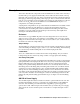
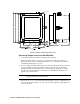
3. Use the conduit hubs at the bottom of the GD-70D4S-XX for routing power and signal
cables into the enclosure. Route a 3-wire power cable (18 AWG) and any relay wiring
through one conduit hub, and 2-conductor shielded cable, or two wires in conduit
through the other conduit hub to minimize crosstalk.
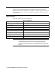
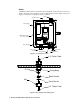
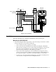
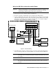
Figure 5: External Wiring
4. If shielded cable is used for controller wiring, connect the signal cable shield’s drain
wire to a chassis ground at the controller, but do not connect it at the GD-70D4S-XX.
CAUTION: Leave the cable shield’s drain wire insulated and disconnected at the
GD-70D4S-XX. You will connect the opposite end of the cable shield’s drain wire at
the controller.
CAUTION: At the controller, do not route power and GD-70D wiring through the same conduit
hub. The power cable may disrupt the transmission of the GD-70D’s signal to the
controller.
1234567
++
--
ALM1DC24V 4-20mA
ALM2 FAULT
+
-
-
+
GD-70D Terminal Strip
89
10
From
Power
Supply
Alarm
Device
Alarm
Device
(+) H
AC Terminal Strip
Strobe
Light
100-240 VAC
HNG
4 - 20 mA In (FB)
- (DC Ground)
Controller
(-) N
External Power
Source
+ (No Connection)
(+) H
(-) N
External Power
Source