Model GD-70D4S-XX Supplement to the GD-70D Operator’s Manual Part Number: 71-0169RK Revision: 0 Released: 3/1/11 www.rkiinstruments.
WARNING Read and understand this instruction manual before operating detector. Improper use of the detector could result in bodily harm or death. Periodic calibration and maintenance of the detector is essential for proper operation and correct readings. Please calibrate and maintain this detector regularly! Frequency of calibration depends upon the type of use you have and the sensor types.
Product Warranty RKI Instruments, Inc. warrants gas alarm equipment sold by us to be free from defects in materials, workmanship, and performance for a period of one year* from the date of shipment from RKI Instruments, Inc. Any parts found defective within that period will be repaired or replaced, at our option, free of charge. Parts must be returned to RKI Instruments, Inc. for repair or replacement.
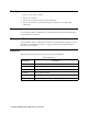
Overview This supplement describes the differences and additional features of the Model GD70D4S-XX compared to the GD-70D. It also describes how to install, startup, maintain, and calibrate the GD-70D4S-XX. See the GD-70D Operator’s Manual for information specific to the GD-70D. Specifications Table 1 lists specifications for the GD-70D4S-XX. Table 1: Specifications Target Gas & Detector Range Refer to the RKI Instruments Inc.
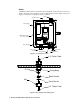
Description This section describes the components of the GD-70D4S-XX. It consists of the enclosure, a GD-70D and a power supply mounted inside, and an amber strobe mounted on the top right side of the enclosure. The “XX” in the part number represents a number that denotes the target gas and changes depending on the target gas. The “S” denotes that the unit runs from AC power and that a strobe is installed. For example, the part number for a detector head for ozone (O3) detection is GD-70D4S-O3.
Strobe A NEMA 4X amber strobe is mounted on the top right side of the enclosure. It is factory wired to the alarm 1 relay terminals on the GD-70D and the 24 VDC output of the power supply so that it turns on during an alarm 1 condition.
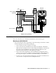
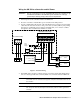
(AC) N L GD-70D Backplate +V -V Strobe Power Supply Terminal BLK BLK DC24V 4-20mA ALM1 ALM2 FAULT 1 5 7 + - + 2 3 4 6 8 9 10 BLK GRN WHT RED BLK GRN AC in Terminal Figure 3: Factory Wiring Installation This section describes how to install the GD-70D4S-XX at the monitoring site. Mounting the GD-70D4S-XX 1. Select a mounting site that is representative of the monitoring environment. Consider the following when you select the mounting site.
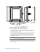
Ø .34, 4X 12.0 11.75 11.23 0.85 MAX 1.43 2.51 7.01 8.22 Inlet Fitting 9.88 3/4" Conduit Hub, 2X Tubing Stub Exhaust Fitting Figure 4: Outline & Mounting Dimensions Connecting Sample Lines to the GD-70D4S-XX 1. Connect the hydrophobic filter to the tubing stub on the inlet. If the hydrophobic filter is not used, or if you install the hydrophobic filter in a different location, replace the tubing stub with 1/4’’ x 1/8’’ tubing as described in “Inlet Fitting Tubing Stub” on page 2. 2.
Wiring the GD-70D to a Controller and AC Power WARNING: Always verify that power to the GD-70D4S-XX and to the controller are off and that the controller’s and GD-70D’s power switches are in the off position before making wiring connections or adjustments. 1. Turn off power to the controller and the GD-70D4S-XX. 2. Place the controller’s and GD-70D’s power switches in the OFF position. 3. Use the conduit hubs at the bottom of the GD-70D4S-XX for routing power and signal cables into the enclosure.
Start Up 1. Turn on power to the controller. 2. Turn on the controller. 3. Turn on power (100 - 240 VAC) to the GD-70D4S-XX. 4. Turn on the GD-70D. See the GD-70D Operator’s Manual for GD-70D startup instructions. Operation See the GD-70D Operator’s Manual for an operational description of the GD-70D that is mounted inside the enclosure. Maintenance/Calibration See the GD-70D Operator’s Manual for maintenance and calibration instructions.