
User Manual


9 • Model GD -70D4H-XX Sampl e Draw Transmitte r
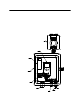
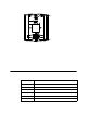
5. Turn the cover over and locate the Audio Select switch at the top of the cover as
shown in the figure below.
Figure 7 : Ho rn/Strobe C over
6. The Audio Select switch can be set at any number between 1 and 6. Numbers 1-3 all
produce an intermittent buzzing sound with 1 being the loudest and 3 bei ng th e
quietest. Numbers 4-6 all produce a steady buzzing sound with 4 being the loudest
and 6 being the quietest. The factory settin g is 2.
7. Turn the Audio Select s witch so that the selection arrow is poin ting to the desired
number.
8. Place the cover over the base and push in and down in order to reinstall the cover.
Make sure that the cover is sealed to the base by the gasket.
9. Screw the captive screw at the bottom front of the horn/strobe back in.
10. Turn on power (100 - 240 VAC) to t h e GX-70D 4H-X X.
11. Turn on the GD-70D. See the GD-70D Operator’s Manual for instructions.
Parts List
Table 4 lists replacement parts and accessories for the GD-70D4H-XX.
Table 2: Parts List
Part Number Description
06-1273RK 1/4” O.D. x 1/8” I.D. Teflon PTFE tubing
17-4820RK Sample fitting, 1/4” tube bulkhead union
18-0107RK 3/4” conduit hu b
49-0108RK Power Supply, 24 VDC
51-0096RK Horn/strobe, 10 - 33 VDC, NEMA 4X
80-0226RK Hydrophobic filter with push fittings for 1/4 inch O.D. tubing
Audio Select Switch
AUDIO
SELECT
6
Strobe Brightness Switch
(DO NOT ADJUST)
1
2
3
4
5
CANDELLA S ELEC T