Model GD-70D4H-XX Supplement to the GD-70D Operator’s Manual Part Number: 71-0268RK Revision: P1 Released: 12/18/12 www.rkiinstruments.
WARNING Read and understand this instruction manual before operating detector. Improper use of the detector could result in bodily harm or death. Periodic calibration and maintenance of the detector is essential for proper operation and correct readings. Please calibrate and maintain this detector regularly! Frequency of calibration depends upon the type of use you have and the sensor types.
Product Warranty RKI Instruments, Inc. warrants gas alarm equipment sold by us to be free from defects in materials, workmanship, and performance for a period of one year* from the date of shipment from RKI Instruments, Inc. Any parts found defective within that period will be repaired or replaced, at our option, free of charge. Parts must be returned to RKI Instruments, Inc. for repair or replacement.
Overview This supplement describes the differences and additional features of the Model GD70D4H-XX compared to the GD-70D. It also describes how to install, startup, maintain, and calibrate the GD-70D4H-XX. See the GD-70D Operator’s Manual for information specific to the GD-70D. Specifications Table 1 lists specifications for the GD-70D4H-XX. Table 1: Specifications Target Gas & Detector Range Refer to the RKI Instruments Inc.
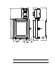
Description This section describes the components of the GD-70D4H-XX. It consists of the enclosure, a GD-70D and a power supply mounted inside, and a horn/strobe mounted on the top right side of the enclosure. The “XX” in the part number represents a number that denotes the target gas and changes depending on the target gas. The “H” denotes that the unit runs from AC power and that a horn/strobe is installed. For example, the part number for a detector head for ozone (O3) detection is GD-70D4H-O3.
Enclosure The enclosure is a type NEMA 4X plastic enclosure designed for use in areas that are subject to rain or hosing down. A mounting foot is installed in each corner. Two sample fittings are mounted on the bottom right of the enclosure and two 3/4” conduit hubs are mounted to the left of the sample fittings. Sample Fittings The inlet fitting is on the bottom right of the enclosure and the exhaust fitting is to the left of the inlet fitting. The fittings accept 1/4”O.D. x 1/8” I.D. Teflon tubing.
GD-70D & Power Supply The GD-70D sample draw detector head is mounted to a plate inside the enclosure. The GD-70D sample fittings are factory connected to the sample fittings on the NEMA 4X enclosure. The GD-70D is powered with 24 VDC supplied by a power supply that operates from a 100 - 240 VAC input. The GD-70D is factory wired to the power supply and to the horn/strobe. See the GD-70D operator’s manual for a complete description of the GD-70D.
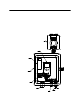
4.83 8.40 8.00 M AX Ø .34, 4X 11.75 11.23 1.43 0.85 M AX 7.01 8.22 9.88 3/4" C onduit Hub, 2X Ex haust Fitti ng 2.51 Inlet F itting Tubing S tub NOTE: A ll D im enions Shown i n Inches Figure 3: Outline & Mounting Dimensions Connecting Sample Lines to the GD-70D4H-XX 1. Connect the hydrophobic filter to the tubing stub on the inlet.
the opposite end of the tubing to an open area where the sample can safely disperse or to an exhaust duct. Wiring the GD-70D to a Controller and AC Power WARNING: Always verify that power to the GD-70D4H-XX and to the controller are off and that the controller’s and GD-70D’s power switches are in the off position before making wiring connections or adjustments. 1. Turn off power to the controller and the GD-70D4H-XX. 2. Place the controller’s and GD-70D’s power switches in the OFF position. 3.
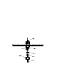
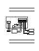
CAUTION: At the controller, do not route power and GD-70D wiring through the same conduit hub. The power cable may disrupt the transmission of the GD-70D’s signal to the controller. 5. Factory wiring is shown below in Figure 5. GD-70D mounting bracket Horn/Strobe (AC) N L +V -V Power Supply Terminal RED + - + - BLK DC 24V 4-20mA ALM 1 ALM 2 FAULT BLK BLK GRN BLK WHT RED GRN AC in Terminal H N G Figure 5: Factory Wiring Start Up 1. Turn on power to the controller. 2.
Operation See the GD-70D Operator’s Manual for an operational description of the GD-70D that is mounted inside the enclosure. Maintenance/Calibration GD-70D Maintenance and Calibration See the GD-70D Operator’s Manual for maintenance and calibration instructions. Use the inlet fitting on the NEMA 4X enclosure to apply gas instead of the fittings inside the enclosure on the GD-70D. Adjusting Horn/Strobe Volume The horn volume on the horn/strobe can be adjusted by doing the following: 1.
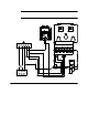
5. Turn the cover over and locate the Audio Select switch at the top of the cover as shown in the figure below. Audio Select Switch 4 5 6 3 2 1 AUDIO SELECT CANDELLA S ELECT Strobe Brightness Switch (DO NOT ADJUST) Figure 7: Horn/Strobe Cover 6. The Audio Select switch can be set at any number between 1 and 6. Numbers 1-3 all produce an intermittent buzzing sound with 1 being the loudest and 3 being the quietest.